Here are the build notes for my Atari Punk Console PCB Design.
Warning! I strongly recommend using old or second hand equipment for your experiments. I am not responsible for any damage to expensive instruments!
If you are new to electronics, see the Getting Started pages.
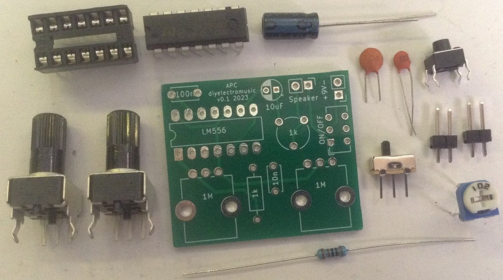
Bill of Materials

- Atari Punk Console PCB (GitHub link below)
- 556 dual timer
- Optional: 14-pin DIP socket
- 1K resistor
- 1K trim potentiometer
- 2x 1M PCB mounted potentiometer
- 100nF ceramic capacitor
- 10nF ceramic capacitor
- 10uF electrolytic capacitor
- slider switch with 2.52mm pin footprint
- Optional: pin headers
- 9V battery clip
- old (30-40Ω recommended) headphone speaker
- Optional: additional current-limiting resistor for speaker (see design notes)
(Note: an extra tactile switch is shown in the photo below – ignore it! It isn’t required :))
Build Steps
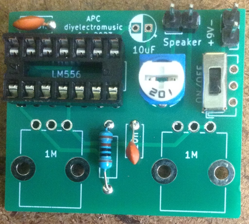
Taking a typical “low to high” soldering approach, this is the suggested order of assembly:
- The resistors.
- DIP socket (if used).
- Disc capacitors.
- Pin headers (if used).
- Slider switch,
- Trim potentiometer.
- Electrolytic capacitor – note the polarity – the negative (short) leg on the filled side, the positive (long) leg on the “+” side.
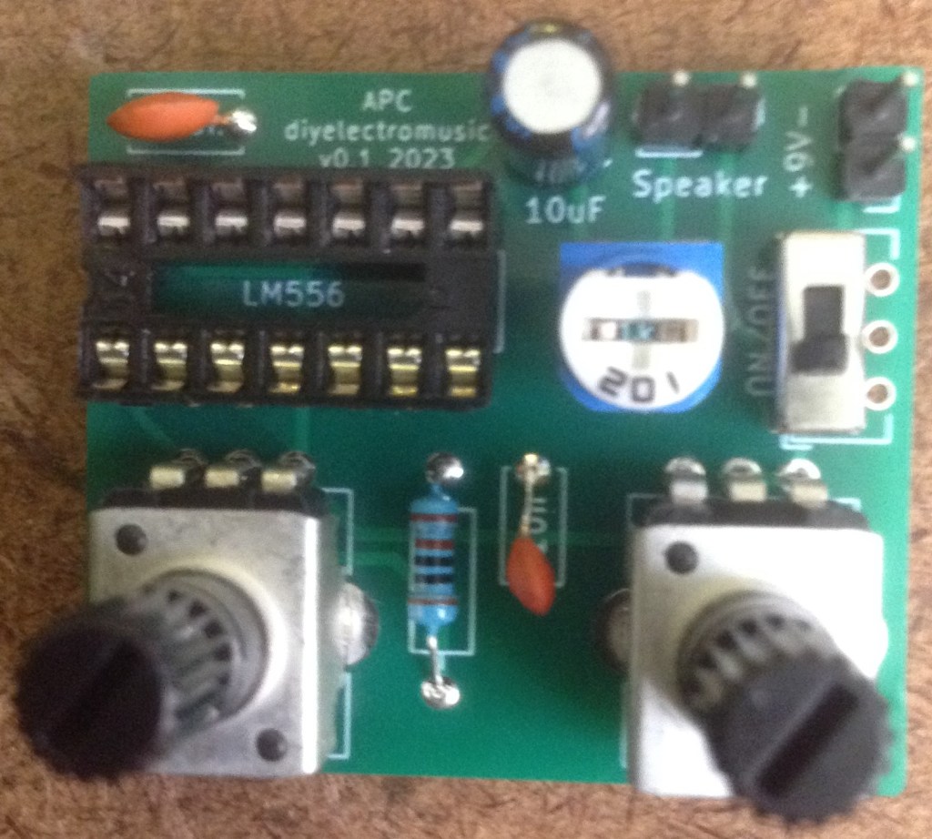
- Potentiometers.
Here are some build photos.


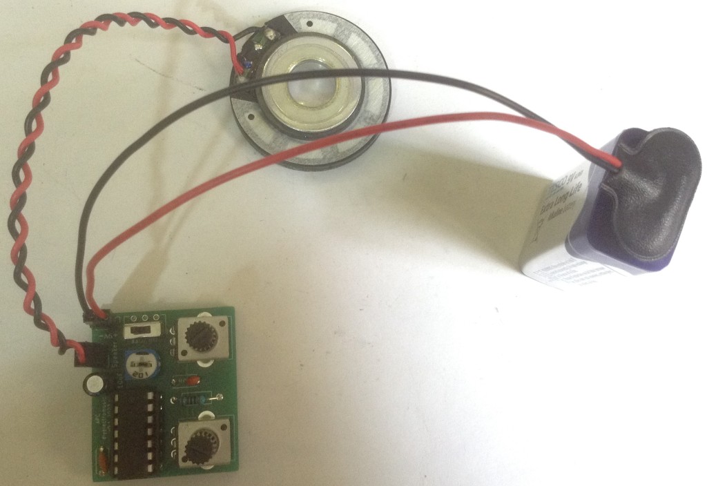
Testing
I recommend performing the general tests described here: PCBs.
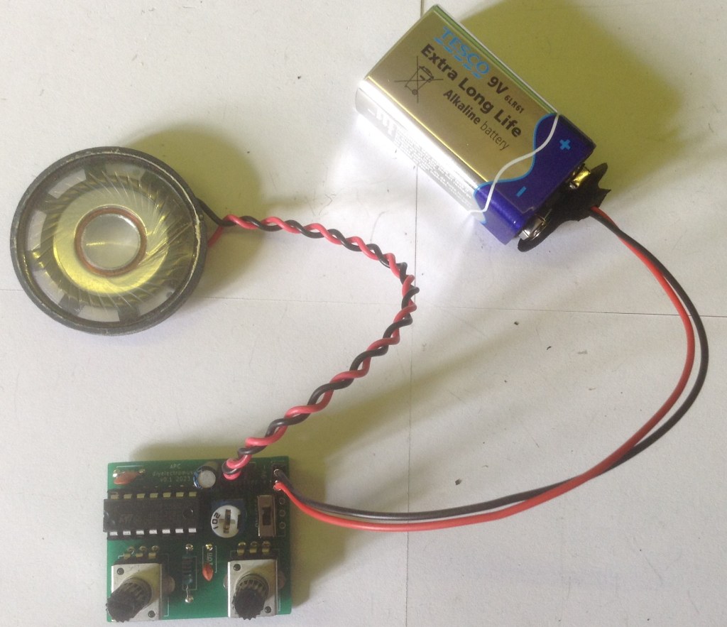
The speaker can probably be connected either way round. The battery naturally must be connected the right way round. Set the trim-pot to the middle of the range and then turn it own and mess with the potentiometers!
Do not connect the speaker output to any other audio equipment or to expensive speakers. It is NOT an audio line level or headphone compatible signal.
PCB Errata
There are no issues currently identified with this PCB.
Find it on GitHub here. Contact me if you’d like the six-board version of the Gerber files!
Closing Thoughts
This seems to work pretty well – or at least comparably well compared to other kits I have!
In terms of future enhancements, I could have done something more complete for the output stage, and I’m not entirely sure I understand the design choice that puts the speaker on the 9V line rather than GND, so there is still plenty to chew over with this simple circuit!
This project is really just a plaything for me, so if you are interested in building your own, I would strongly recommend buying an off-the-shelf kit with a good pedigree rather than my relatively simple efforts here!
But now that I have a number of these PCBs to play with, I can go and see what else I might be able to do with them! Basically this was a one of those “wheels” I’ve been thinking about “reinventing” for a while now, so it is nice to actually have something to show for it 🙂
These boards have been manufactured using the Seeed Fusion PCB service, which I am happy to continue to recommend. They have been supported with discount vouchers that I’ve been sent by Seeed for my previous projects.
Kevin