I’ve been experimenting with various options for getting 16 tone generators running with MiniDexed and one of the options is running two MiniDexed setups side by side. I have a fork of MiniDexed that will allow one MiniDexed UI to control the 8 tone generators of a second MiniDexed over MIDI, but I’ll come back to that in a future post.
So this PCB is a pretty niche application but it makes what I’m trying to do a lot easier and allows two Raspberry Pis running MiniDexed to be connected in the same physical unit.
The build guide can be found here: RPi Dual MiniDexed PCB – Part 2.
Warning! I strongly recommend using old or second hand equipment for your experiments. I am not responsible for any damage to expensive instruments!
These are the key tutorials for the main concepts used in this project:
If you are new to microcontrollers, see the Getting Started pages.
The Circuit
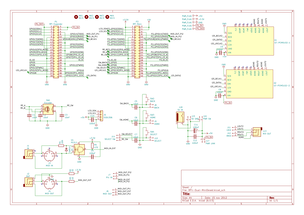
This perhaps isn’t particularly easy to spot what is going on, so maybe this sketch might help a little.
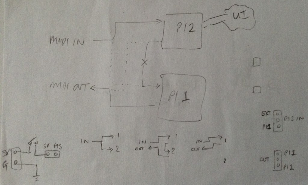
Basically, there is one Pi with an external MIDI interface and a full user interface: SSD1306 display, rotary encoder, buttons; and a second Pi that has its MIDI IN connected to the first Pis MIDI OUT via a direct UART link. Both Pis have their own PCM5102 module for audio output which will need to be mixed.
I’ve left the board with jumper settings for the MIDI routing. The following are all options:
- MIDI IN -> Main Pi; Main Pi MIDI OUT -> Expander Pi MIDI IN; Expander MIDI OUT -> MIDI OUT – this is the proper “dual mode” the board was made for.
- MIDI IN -> Both Pis – this gives two parallel MiniDexeds, both receiving the same MIDI IN feed, but with nothing going between them.
- MIDI IN -> Main Pi; Main Pi-> MIDI OUT – for when just a single Pi is connected (e.g. for testing).
There is also a 5V barrel jack input and header connector and an optional power switch, which can be set to power both Pis via their 5V GPIO lines. This has to be a regulated, stable 5V supply able to provide enough current to power two Raspberry Pis of course… If not, then the Pis can be powered independently via their own USB supplies and there is a jumper to isolate the two 5V sides to allow this.
Note that there is no isolation between the UARTs of the two boards though, but regardless of the power mode they share a common GND connection.
All power for the UI and external MIDI interface comes from the main Pi, but the PCM 5102 modules are powered from the 5V of the PI that is driving them.
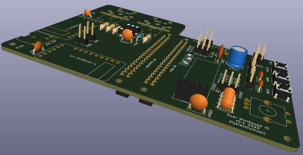
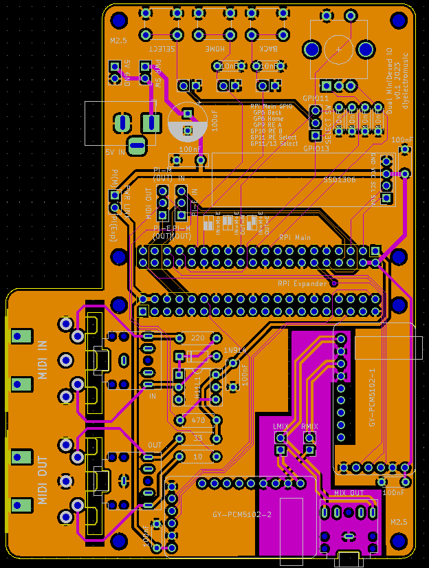
PCB Design
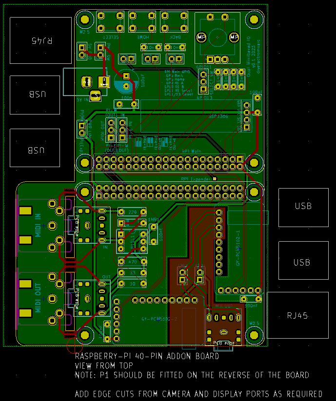
I’ve used the template for a Raspberry Pi add-on board and duplicated (and rotated) the physical footprint to give me two Pi’s “back to back”. The main issue is keeping the power supply routing sensible and making sure the right power signal goes to the right parts of the board.
The PCM5102 modules have additional header pins (that I usually don’t use) that include the audio L/R out. I’ve combined the two signals from the two modules via a simple passive mixer, broken out to an additional audio TRS socket. Alternatively the two independent TRS outputs (one for each module) can be used and externally mixed if preferred. There are jumpers that can disconnect to the outputs to allow for this.
I’ve not included additional resistors in the passive mixer circuit as the modules themselves already include resistors in their output circuits. I did think it was prudent to keep the GND area for the audio section independent of the GND plane for the digital side. But as I’m not an electronics person, feel free to let me know if this was a good thought or not (or what to do better).
I’ve included the footprints for either DIN or TRS MIDI sockets. The DIN footprints are on the underside of the board and can be physically removed if not required. If using the PCB with two Pi 3A+s then only using TRS MIDI would make for quite a compact unit.
I’ve included a list of GPIO pins used and some helper diagrams for the MIDI jumper settings on the silkscreen. I’m not totally convinced they work – I still have to remember quite what I was meaning – but it’s better than nothing I suppose.
Closing Thoughts
So far, the board appears to do everything I hoping. It is quite a niche application and requires a special build of firmware for MiniDexed, but more on that later.
These boards have been sent to be manufactured by the Seeed Fusion PCB service, which I am happy to continue to recommend. They have been supported with discount vouchers that I’ve been sent by Seeed for my previous projects.
Kevin
