This is a re-design of my 3V3 MIDI Module PCB and Arduino MIDI Proto Shield for the Seeed Studio XIAO series of microcontrollers.
Build Guide: XIAO MIDI Proto PCB – Part 2.
Warning! I strongly recommend using old or second hand equipment for your experiments. I am not responsible for any damage to expensive instruments!
These are the key tutorials for the main concepts used in this project:
If you are new to microcontrollers, see the Getting Started pages.
The Circuit
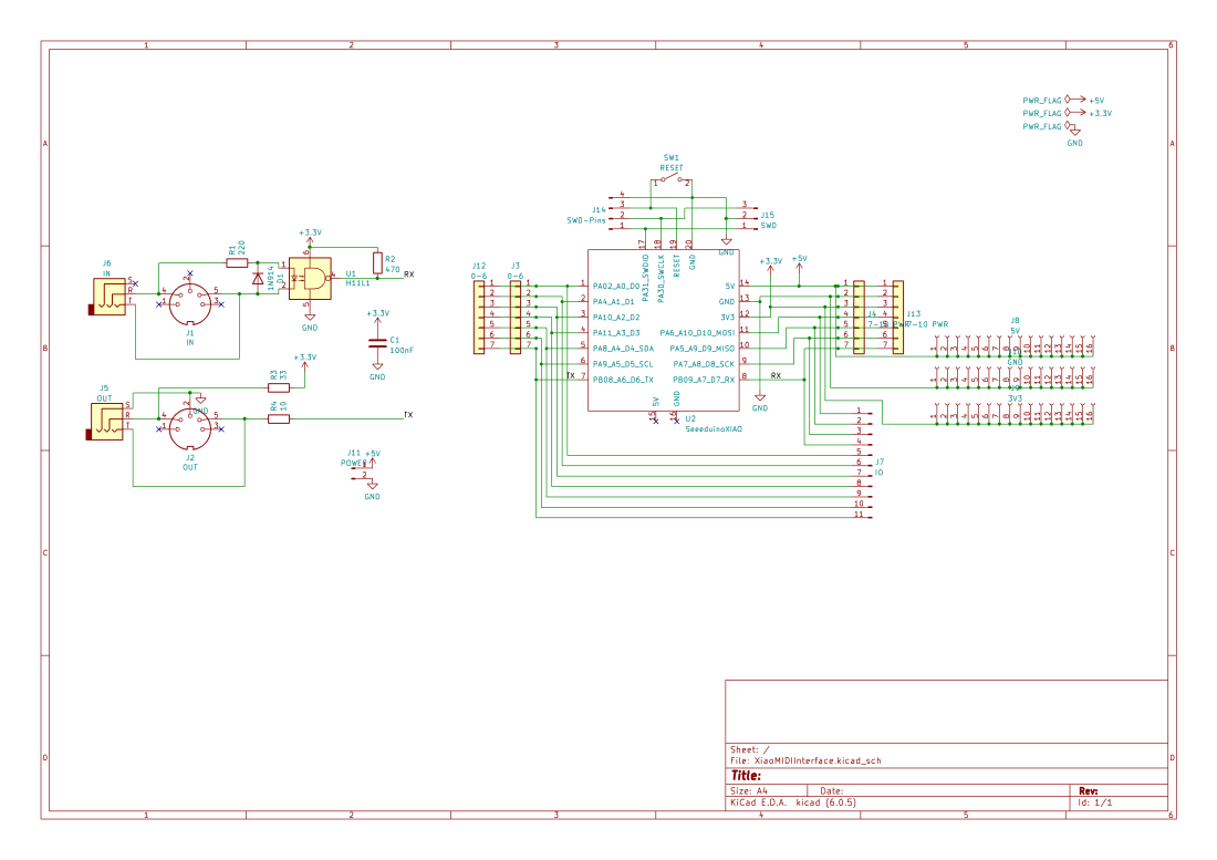
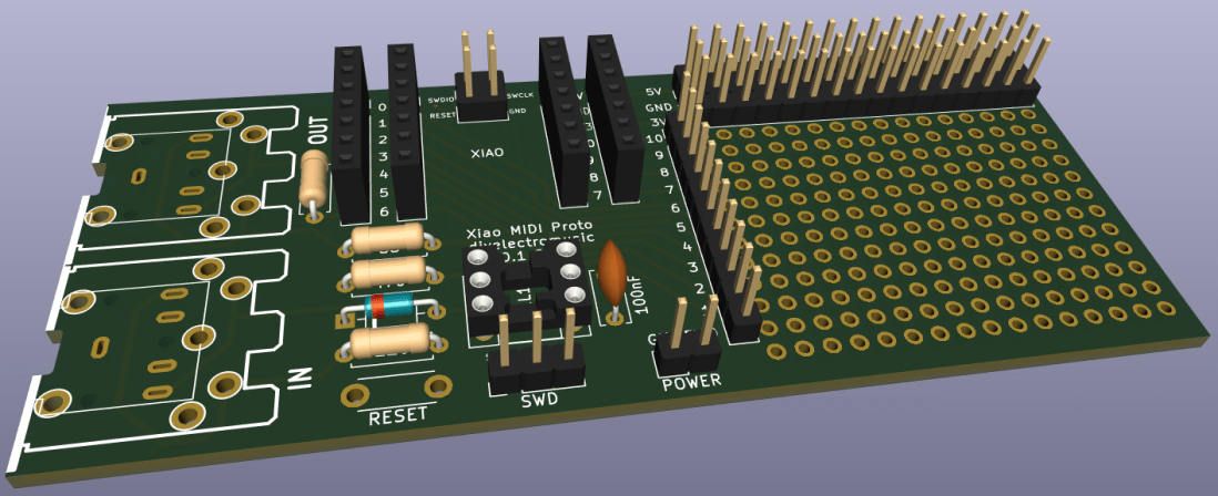
The MIDI side is my standard 3V3 MIDI circuit with a H11L1 optoisolator on the MIDI IN side and an unbuffered 3V3 compatible MIDI OUT stage. The board can be populated with either MIDI DIN or MIDI TRS (type A wiring) sockets. The MIDI OUT circuit is a deliberately non-buffered, 3V3 compatible circuit.
There is also a set of prototyping headers, additional header pins for the XIAO and a reset switch and SWD set of headers. The latter are modelled of the XIAO expansion board, including the anticipated use of “pogo-pins” to connect to the four SWD/Reset pads on the underside of the XIAO.
The circuit is compatible with the following in the XIAO series:
- XIAO SAMD21
- XIAO RP2040
- XIAO ESP32C3
- Other XIAO Series – Untested – probably but NOT the ESP32S3 Sense.
- Adafruit QT Py Series – Untested – possibly but with limitations.
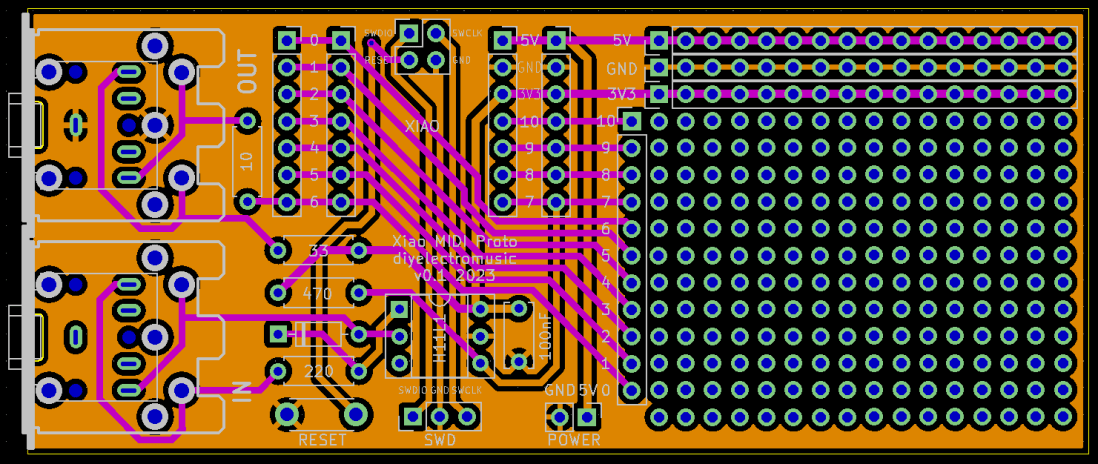
PCB Design
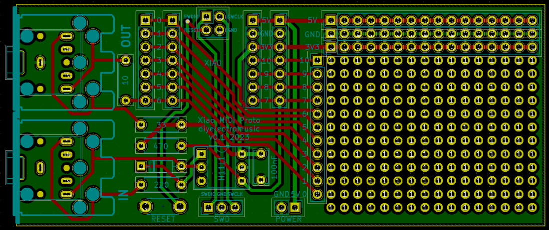
XIAO pins A6/A7 (TX/RX) connect to the MIDI interface. All other XIAO pins are broken out to a set of header connections alongside the prototyping area as well as there being two additional sets of XIAO pin headers.
At the top of the prototyping area are rows of pads for 5V, GND and 3V3.
There is a reset switch, SWD headers and headers for external 5V power too.
Note that as already mentioned the SWD and reset switch require the use of “pogo-pin” header connections on the underside of the XIAO, just like those used on the XIAO expansion board.
NOTE: The PCB should be pin-out compatible with the Adafruit QT Py series boards too, but only if the pogo-pins are left unpopulated as these boards don’t have pads (or don’t have them in the same place) on the underside of the board.
Errata: The silkscreen labels for the IO breakouts near the prototyping area for A0 to A6 are back to front. Pin 6 is actually at the bottom and pin 0 is next to pin 7.
Closing Thoughts
This is the first of a range of XIAO PCBs to build on my posts for the XIAO SAMD21, Arduino and MIDI.
These boards have been sent for manufacturing using the Seeed Fusion PCB service, which I am happy to continue to recommend. They have been supported with discount vouchers that I’ve been sent by Seeed for my previous projects.
Kevin
