Despite saying last time that I looked at the YM2413, I didn’t need to build a protoboard version of the YM2413 “shield”, I’ve had an idea for something that would really benefit from one, so here it is.
I’ve built it onto one of my Arduino MIDI Proto Shields.
Warning! I strongly recommend using old or second hand equipment for your experiments. I am not responsible for any damage to expensive instruments!
These are the key Arduino tutorials for the main concepts used in this project:
If you are new to Arduino, see the Getting Started pages.
Parts list
- Arduino Uno
- Arduino MIDI Proto Shield (any version) or stripboard or proto shield
- YM2413
- Optional: 18-way DIP socket
- 2x2K2, 2x4K7 resistors
- 1x10K potentiometer
- 2x27pF, 1x100nF ceramic capacitors
- 1x 220uF electrolytic capacitor
- 1x10uF electrolytic or non-polar capacitor
- 1×3.5795MHz oscillator
- 3.5mm jack socket
- Jumper wires
The Circuit

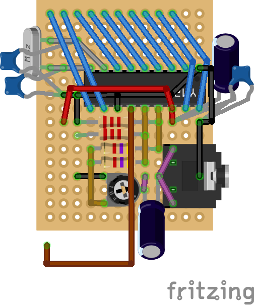
This is the same circuit that I used before, but the connection to the Arduino is slightly different to making routing the wires easier. The right hand diagram is the same circuit but without the protoshield present, just to make it a little easier to follow.
Once again, I’m not going to go into much detail about the YM2413 or the circuit as I discuss it quite a bit in the previous post.
The Arduino interface now is as follows:
 YM2413  Arduino
 D0 (17)   D3
 D1 (18)   D2
 D2 (2)    D4
 D3 (3)    D5
 D4 (4)    D6
 D5 (5)    D7
 D6 (6)    D8
 D7 (7)    D9
 A0 (10)   D11
/WE (11)   D10
/CS (12)   GND
I built mine up on one of my Arduino MIDI Proto Shields. In this case, I’ve used a “V3” shield with the additional IO breakouts around the edge, but any will do.
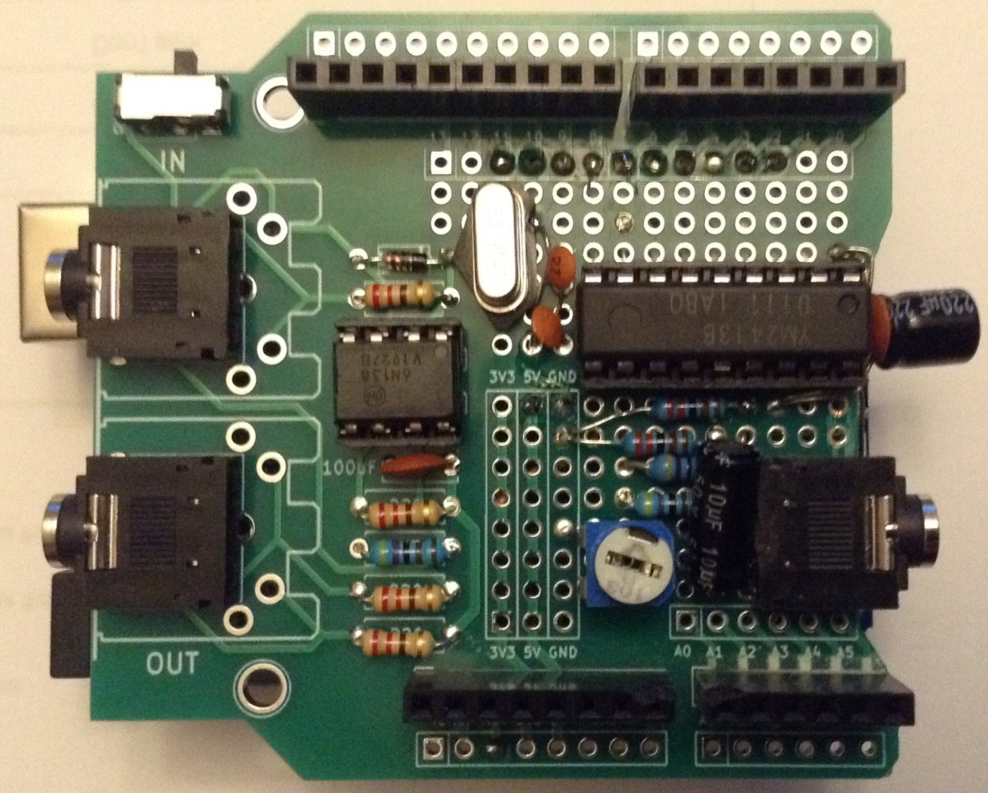
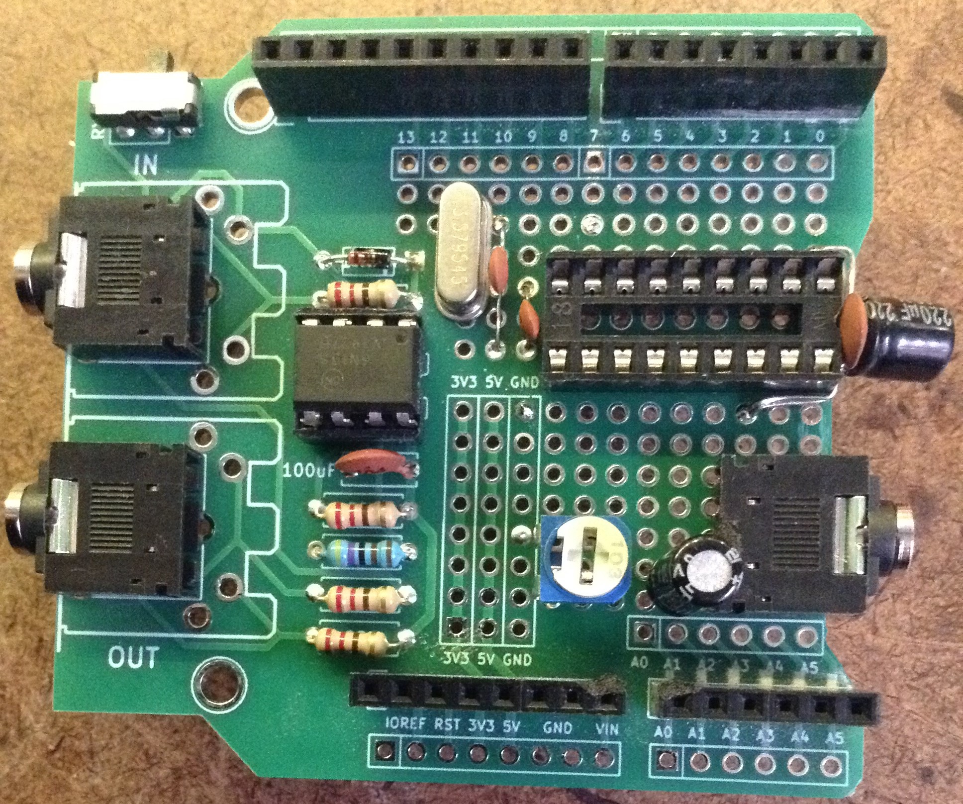
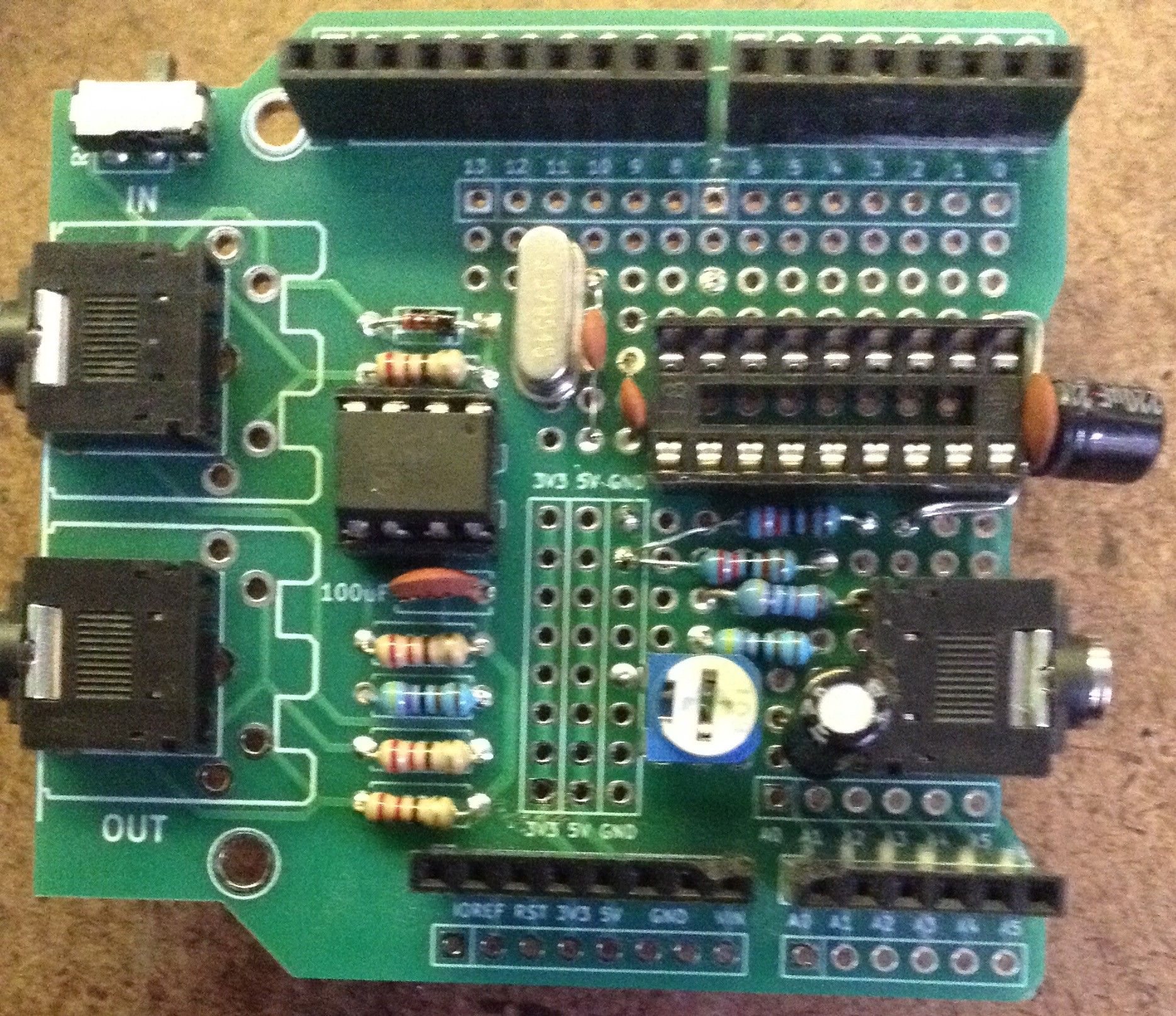
Here are some photos of the build.
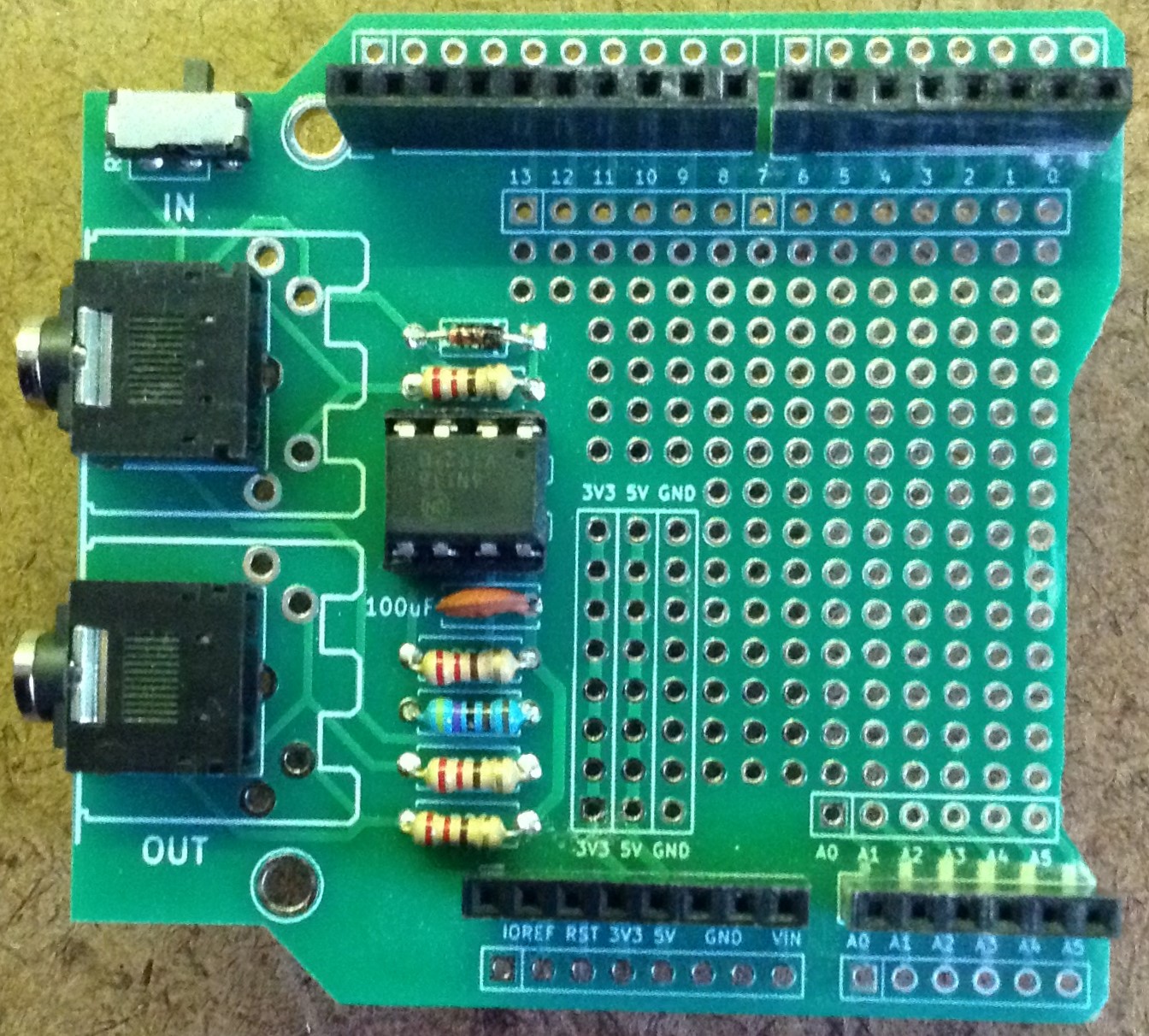

I have to trim off part of the proto PCB to allow the 3.5mm socket to fit properly. In the above (right) photo I’m just checking the key component placements for their correct positioning.
Then I started soldering in the following order:
- DIP and 3.5mm sockets.
- Oscillator and capacitors.
- Pot and non-polar electrolytic.
- Resistors.
- Connecting wires.

Rather than mount the decoupling capacitors for the YM2413 on the PCB, I bend the leads around to mount them slightly “off board” as shown below. When mounting the oscillator, be wary of shorts via the metal casing.
At this point the GND connections to the capacitors and YM2413 are made too, although I forgot one and had to patch it in later, so the link to pin 12 (/CS) is missing in the photo below.

Next up is the pot and non-polar capacitor which outputs to the 3.5mm socket. The pot’s wiper is connected to the capacitor, and the top leg of the pot connects to GND (I just bent the leg over underneath to solder bridge across).

The resistors complete the output part of the circuit. Note: two are linking to GND and two are linking to the pot.
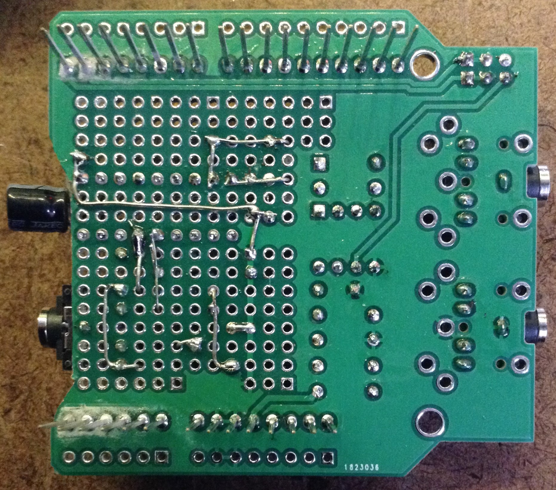
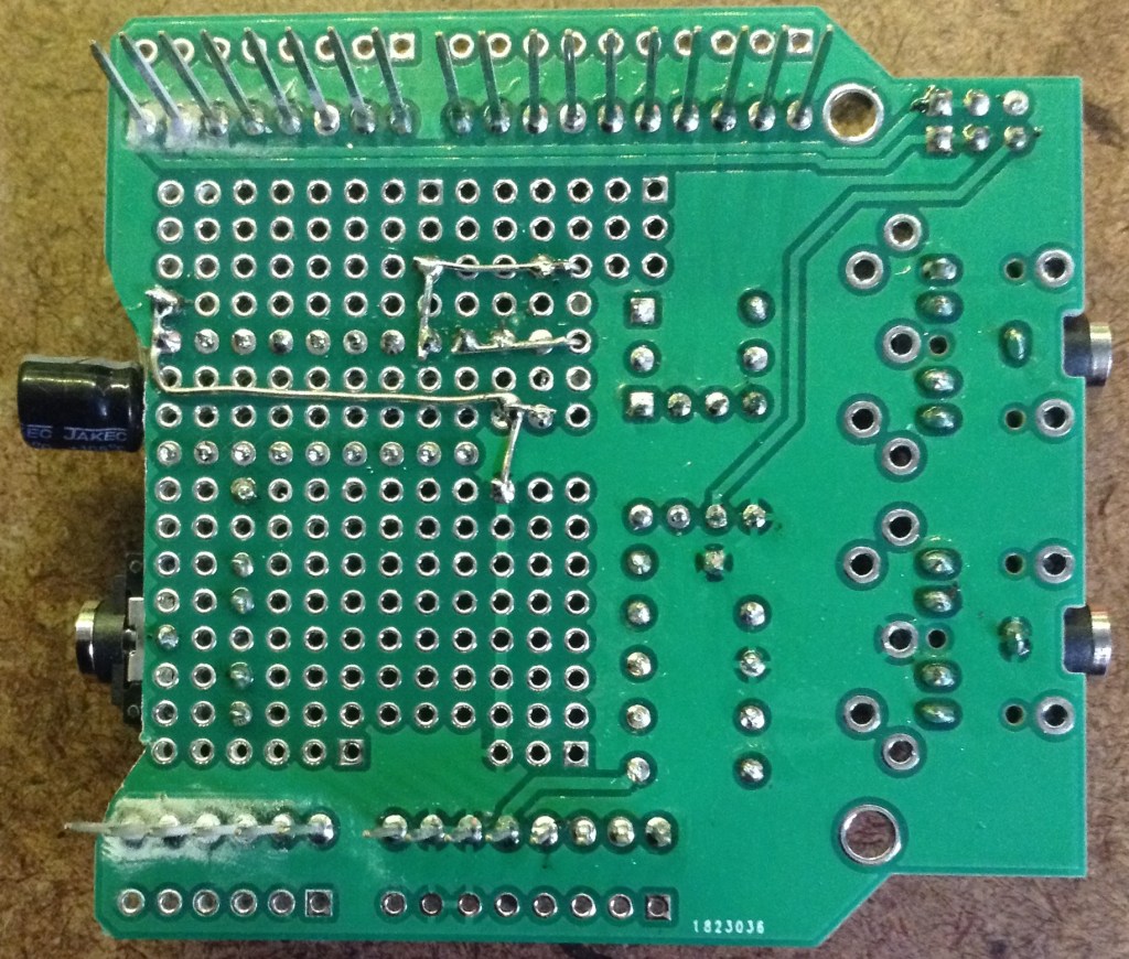
At this point the final GND connection to the 3.5mm socket, 5V and the reset line from the YM24213 to the Arduino are made using wires on the underside of the board.
As I’m using a “V3” proto shield, I can just route the reset wire around the pins to the additional breakout on the outside of the board. If a different proto-shield is used, or stripboard, then an alternative layout will be required.

As this point I spotted that I’d forgotten one of the GND links to the YM2413, so I temporarily move the 5V wire out of the way to make that link.

Finally the data lines, A0 and /WE can be linked up as follows.

After some basic tests, all seemed well so I plugged in the YM2413 and fired it up.
There was a problem though. It worked, but everything sounded very weird! I won’t go over the full debugging process, but I went back to first principles and eventually got to testing that the data pins were all routed correctly. It turns out that D1 on the YM2413, connected to D2 on the Arduino, was always 0. This means that whenever data was sent across to the chip from the Arduino, the values all had D1 set to 0.
The issue turned out to be a short between pin 18 on the YM2413 and the GND plane in that portion of the board at the point where I’d trimmed the PCB to allow the 3.5mm socket to fit! A bit of filing and poking solved the problem.
The Code
Once again, a full description of the code was provided last time, so I’ll not go into it again here. A good starting point again is Marco’s MD_YM2413_Custom example code. Or you can use my code from last time.
Either way, the only change required is to configure the Arduino pins appropriately as shown below.
const uint8_t D_PIN[] = { 3, 2, 4, 5, 6, 7, 8, 9 };
const uint8_t WE_PIN = 10;
const uint8_t A0_PIN = 11;
Closing Thoughts
Although I said last time that I didn’t need to build a proto board version, I have an idea for something I want to do that I can’t do with Marco’s shield and rather than mess around with solderless breadboard, I thought it worth the time to make a shield.
But I’ll come on to that another time.
Kevin
