As Arduino MIDI Interfaces are so common in most of my builds, I decided to build a “stackable” module. This was partly triggered by the release recently of the official Arduino “Make Your Uno” kit which comes with a synth shield you can build. But it doesn’t have MIDI so I thought something like this would pair up really nicely with the official Arduino synth shield.
I did wonder about having “hanging out” MIDI sockets (like I used in my MiniDexed IO board), but then switched to a design using TRS sockets, which are pretty low-profile, especially in PCB mounting form.
This design repurposes my Arduino MIDI Proto Shield but rewiring the DIN MIDI sockets to TRS ports.
Update: There is now a version of the Arduino MIDI Proto Shield that includes the option to use TRS sockets instead of DIN sockets.
Warning! I strongly recommend using an old or second hand keyboard for your MIDI experiments. I am not responsible for any damage to expensive instruments!
These are the key Arduino tutorials for the main concepts used in this project:
If you are new to Arduino, see the Getting Started pages.
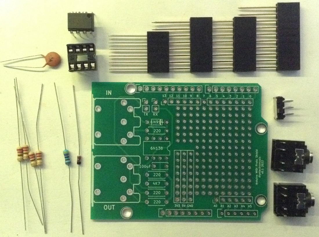
Parts list
- Arduino Uno
- Arduino MIDI Proto Shield
- 1x 6N138 optoisolator
- 4x 220Ω resistors
- 1x 4k7Ω resistor
- 1x 1N914 or 1N4148 signal diode or similar
- 1x 100nF capacitor
- 2x stereo TRS sockets
- 1x DPDT switch or jumper headers
- Set of Arduino extended headers: 1x 6 way; 2x 8 way; 1x 10 way
- Optional: 8-way DIP socket
- Jumper wires
The Circuit
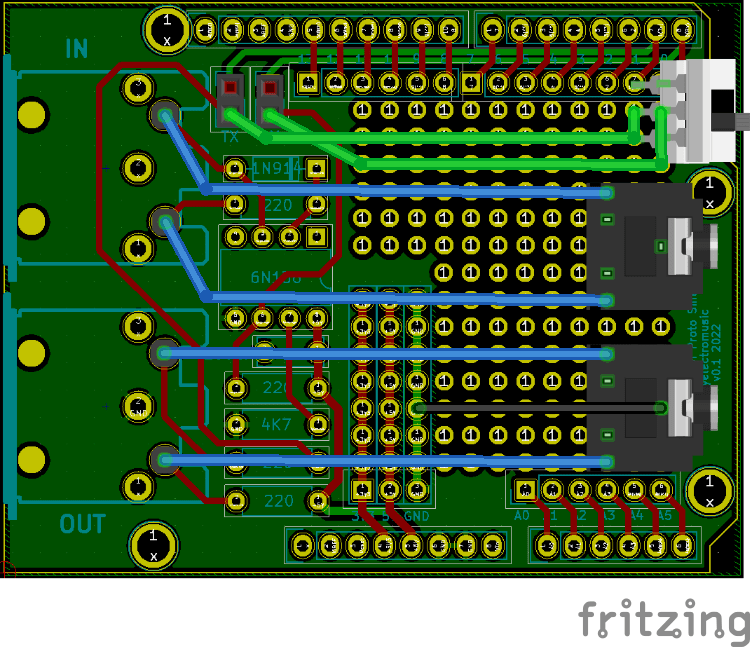
The diagram above shows how the Arduino MIDI Proto Shield can be adjusted to use TRS sockets instead of DIN sockets.
There is nothing particular special about this circuit though, it is the standard 5V MIDI IN/OUT circuit I’ve used in pretty much all of my Arduino MIDI Interfaces.
Build Guide
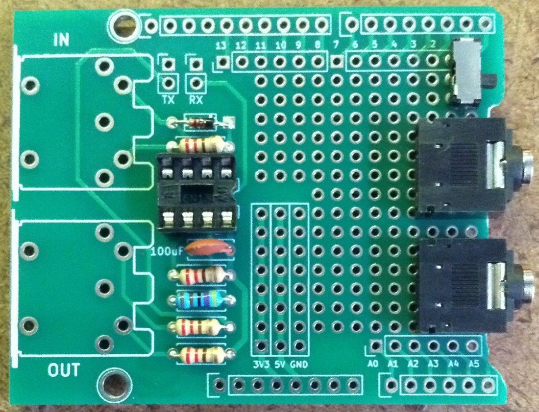
This could be built on protoboard or even stripboard, but the point of this project for me is to use my Arduino MIDI Proto Shield, so here are the build notes for that.
The first step is to trim the PCB slightly. The PCB mounted TRS sockets I’m using ideally have a cut-out where the jack plug goes in the socket. To allow them to fit snugly onto my proto PCB I ended up cutting away a small part of the PCB as shown below. Basically cut away the identifying text between the two mounting holes!

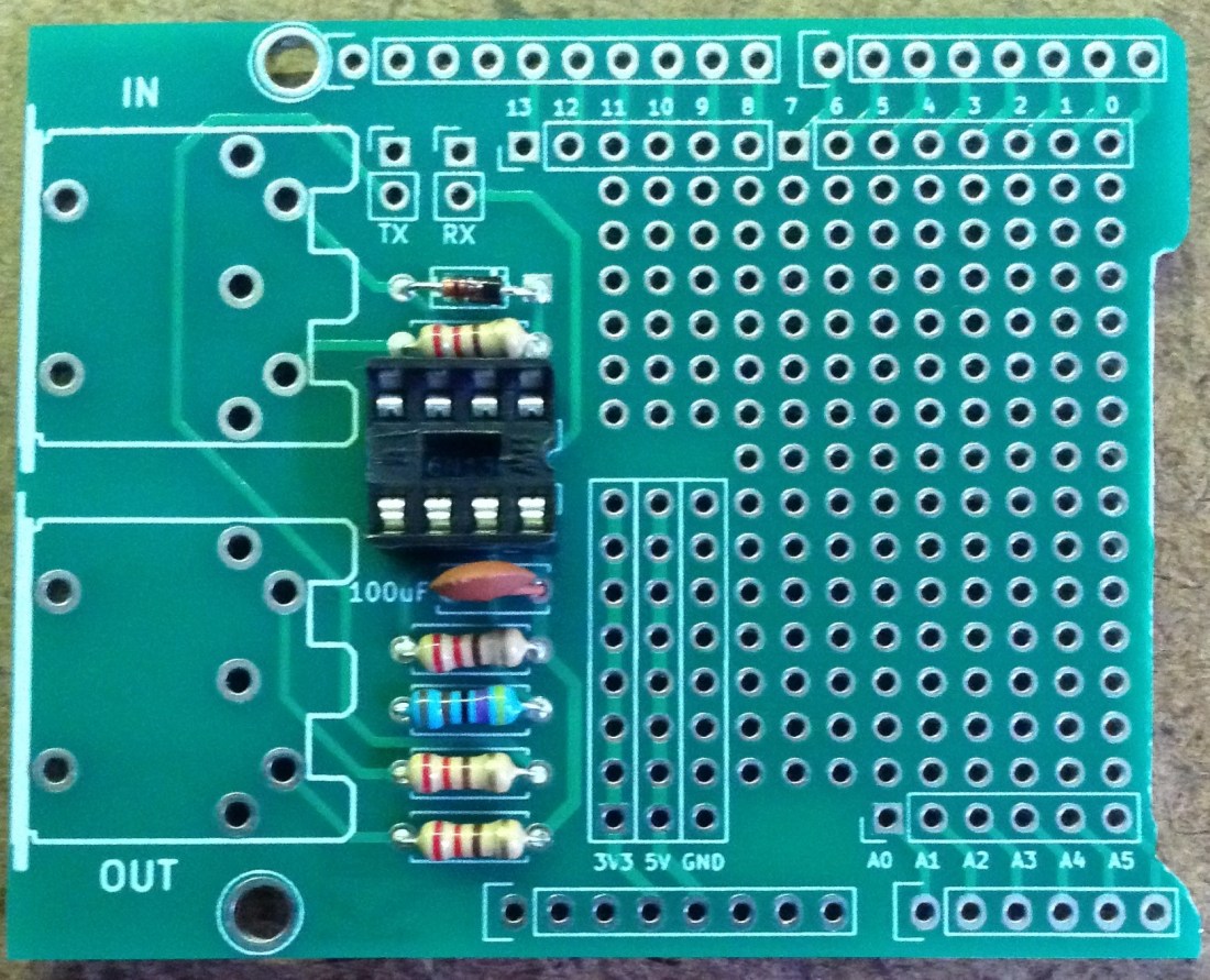
Next the simplest thing is to solder the MIDI circuit as follows:
- Solder the resistors and diode.
- Solder the 8-way DIP socket.
- Solder the 100nF capacitor.
Then the two TRS sockets and the DPDT switch can be added. The DPDT switch could be replaced by the existing two 2-way header pins and jumpers if required (this is what they are there for!). Or it could even be omitted altogether if required, but I recommend having something that allows the RX/TX to be disconnected from the MIDI circuit in order to allow sketches to be uploaded to the Arduino.
The reason I’ve not used the existing headers is that I want to be able to use this shield underneath another one, so the jumpers wouldn’t be very accessible when everything is fitted together. A neat switch brought out to the edge of the board makes it a lot more usable.
At this point the sockets and switch need connecting to the rest of the circuit. Using the MIDI Connections Cheat Sheet we can see which pins of the TRS sockets should be driven by which pins from the DIN sockets. The OUT socket also needs a GND connection, which I chose to link up on the underside of the board.


The last step is the solder on the extended headers. As always if you are able to use another shield as a temporary “header holder” to keep the headers in position whilst connecting them, that will make things a lot easier to build.
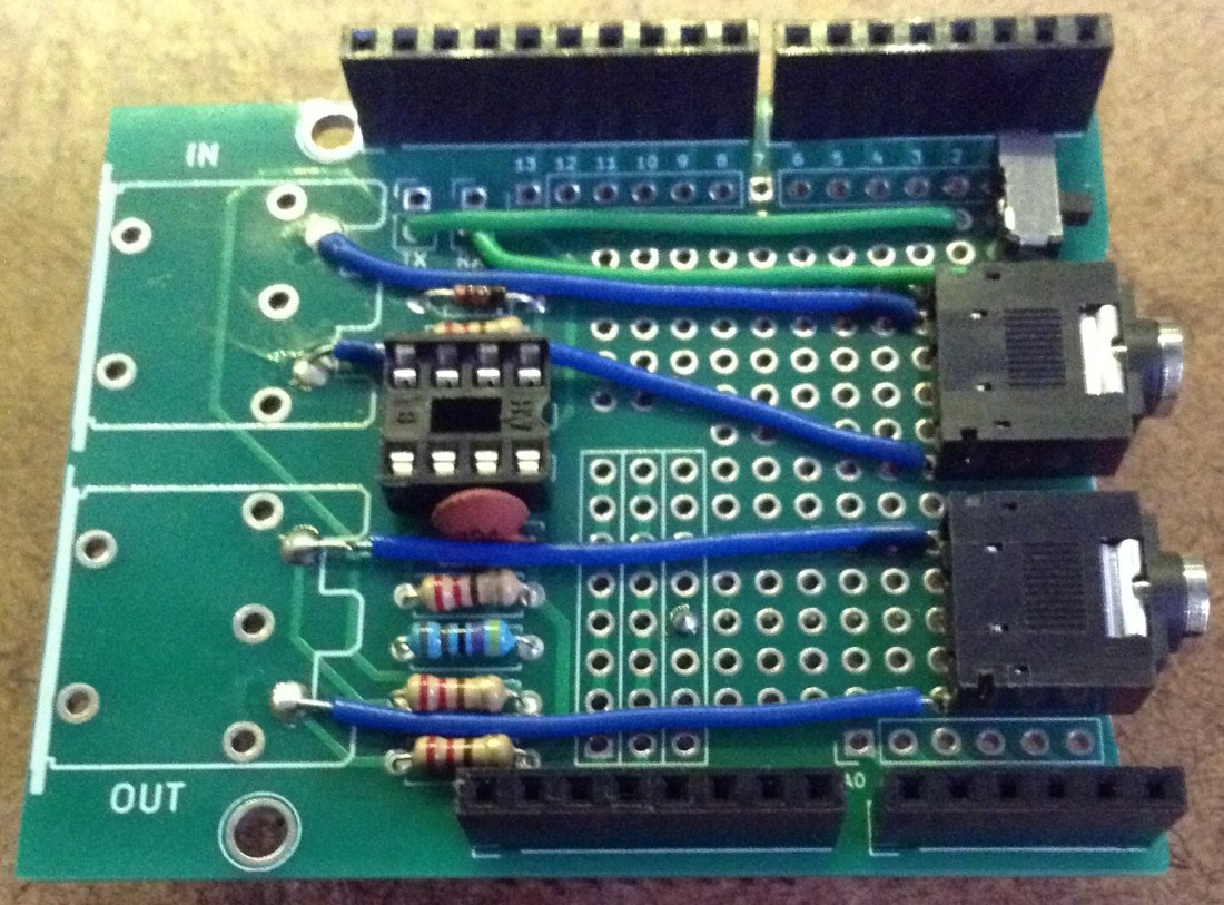
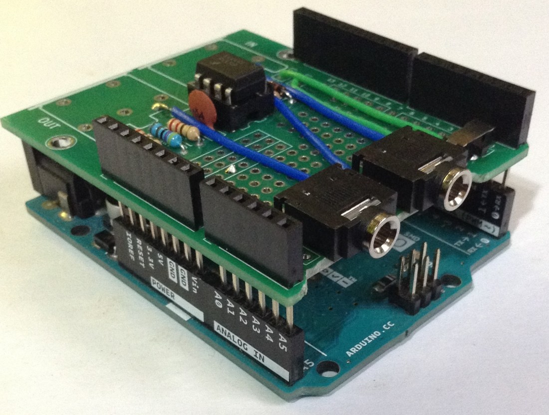
Finally here are two photos of the board plugged into an Arduino Uno and then with one of my older “synth shields” on top.


The Code
Any demonstration code using the Arduino MIDI Library could be used. A simple test is to use my Simple MIDI Monitor which will do two things:
- Flash the on-board LED when a note is being played over MIDI.
- Automatically pass anything received on the MIDI IN over to the MIDI OUT port.
This means that connecting the board as follows makes for a pretty complete test of the unit:
- MIDI keyboard controller -> Arduino MIDI IN.
- Arduino MIDI OUT -> synth module.
If all is working playing the MIDI controller will result in the synth module playing notes, but also that the Arduino LED will come on every time a note is played.
Closing Thoughts
The trigger for putting this together was to think about how this could be used with boards like the official Arduino “Make Your Uno” synth shield to provide MIDI connectivity whilst maintaining access to the controls of the synth shield. I think it should do that pretty well.
I’d love to show you a photo of it in use with the official Arduino synth shield, but I don’t have one and they are quite expensive to post to the UK at present.
But if those costs drop a little, then maybe I’ll look into it, as it does look like quite a bit of fun.
Kevin

Hi Kevin! Thanks for making this cool project! I’ve been searching through your github but cannot find any code to run this on the arduino. Do I use a generic midi controller code or did you write one specifically to interface with the Atari?
LikeLike
If you’re referring to my “Atari Synth Cart Controller” then the code is explained and linked to from that post: https://diyelectromusic.com/2025/12/13/atari-synth-cart-controller/
This could use any MIDI interface, it doesn’t need to be my TRS one, but it does need a fair bit of special code to emulate the Atari controllers to drive the Synth Cart.
If you’re meaning something else, just let me know and I’ll see what I can do.
Kevin
LikeLike