I have a number of Arduino projects that allow for some kind of synthesis to be output via a digital to analog conversion process. This PCB brings three of those methods together into a single shield to support a range of experiments.

Warning! I strongly recommend using old or second hand equipment for your experiments. I am not responsible for any damage to expensive instruments!
These are the key Arduino tutorials for the main concepts used in this project:
If you are new to Arduino, see the Getting Started pages.
The Circuit
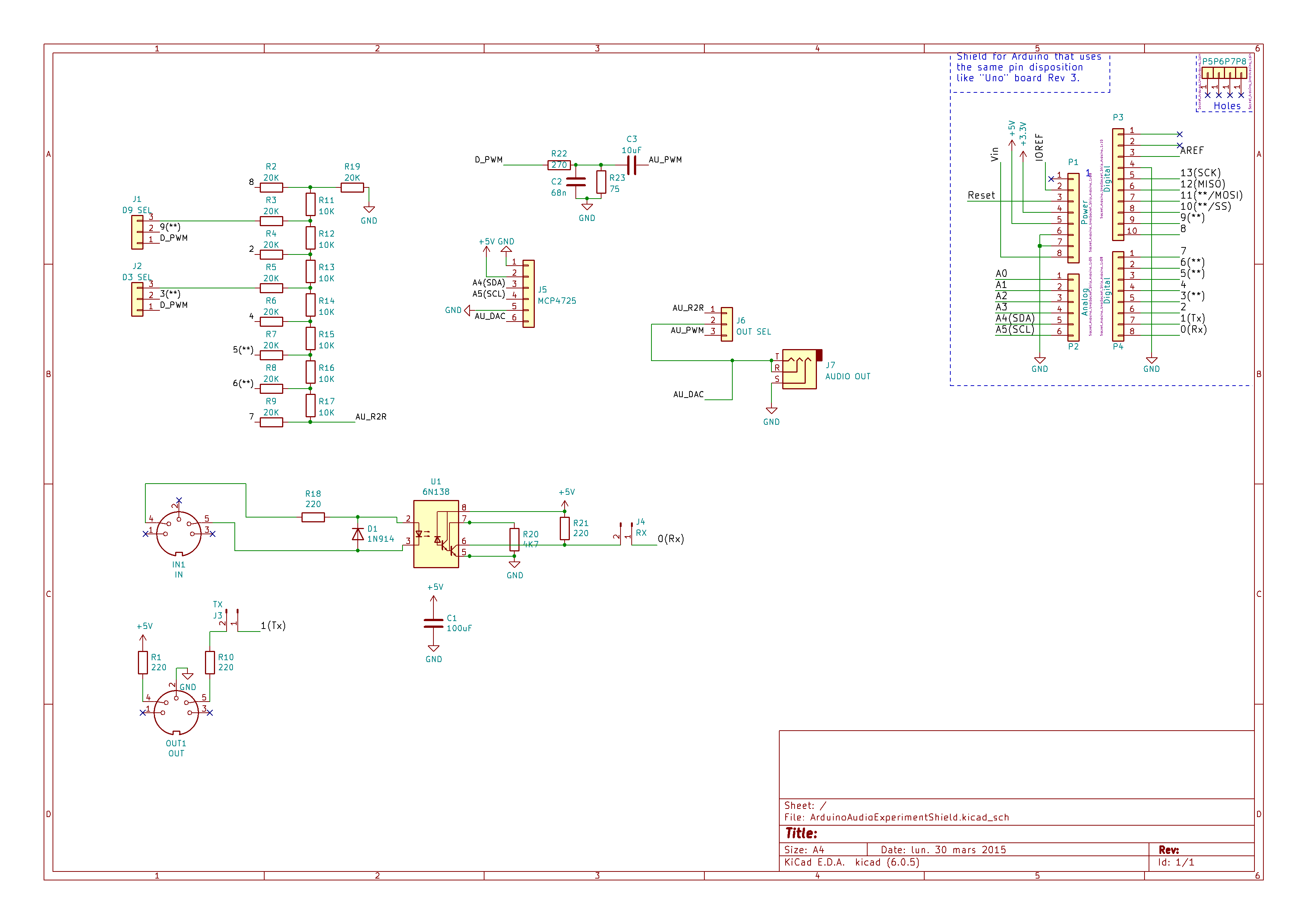
This supports the following methods for audio output, but they are not designed to be used at the same time!
- Arduino PWM output on D3 or D9. D9 is the default used by Mozzi.
- An 8-bit R2R resistor digital to analog converter using D2 to D9. Cannot be used at the same time as PWM output.
- MCP4725 I2C DAC.
It also includes a filter for the PWM output, MIDI IN and OUT circuitry (connected to D0 and D1) and a jack socket for audio output. There are a range of jumpers to select the various functions of the shield when in use.
PCB Design
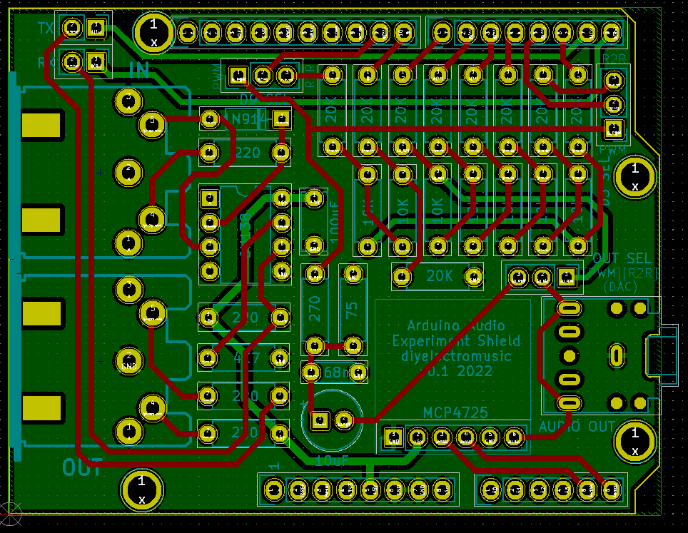
There are four key sections of the board: MIDI, R2R, PWM, and the MCP4725, are highlighted below:

There are a number of configuration jumpers:
- Top left, the TX and RX jumpers enable or disable the MIDI links to TX/RX. The MIDI links have to be disabled to allow sketches to be uploaded to the connected Arduino.
- Top centre and top right, there are two jumpers that configure what D9 (centre) and D3 (right) are connected to: either the PWM output circuit or the R2R ladder. If using PWM then it is expected that only one will be connected at any one time.
- Centre right there is a jumper to determine what gets connected to the audio output jack socket. This chooses between: PWM (jumper on the left), R2R (jumper on the right), or the MCP4725 DAC (jumper removed). There is no jumper to disable to DAC so the assumption is that the DAC would probably be socketed and simply removed if not in use.
- The values in the PWM circuit are not optimal. See discussion here: Arduino PWM Output Filter Circuit.
Note that the MCP4725 DAC is using the I2C interface on A4/A5 not the additional SDA/SCL header pins.

Closing Thoughts
Whilst I know all the individual elements of this board work from previous projects, there is a little apprehension for bringing them all together, so I now have to wait until I get the boards back to see how it all works out.
This is one of two boards I’ve now sent off to Seeed Fusion for manufacturing, using some discount vouchers I’ve been sent.
Kevin

hello i have approximatively the same project but I had some questions can you help me ?
LikeLike
I can’t make any promises, but feel free to ask away and I’ll see what I can do (generally I only really answer questions about things related to my own projects).
LikeLike
Hello,Thanks . This is mine but I have a problem with the pwm I can See the signal well. I add some push Button for changing the form of the signalÂ
We divide it like this but it didnât work wellÂ
Envoyé depuis Yahoo Mail pour iPhone
LikeLike
Sorry, I’m not entirely sure I understand what your issue is? Do you have a link to your project?
Kevin
LikeLike