This is a continuation of my exploration of MiniDexed. In part 1 I built a basic breadboard version. In this part, I’ve built a DIY “MiniDexed HAT” for a 40-way GPIO Raspberry Pi.
Update: There is also now a custom PCB too: MiniDexed Raspberry Pi IO Board.
Warning! I strongly recommend using old or second hand equipment for your experiments. I am not responsible for any damage to expensive instruments!
These are the key tutorials for the main concepts used in this project:
- “Bare Metal” Raspberry Pi MiniDexed DX7
- MiniDexed Wiki
- MIDIDEXED – honey, I shrunk my DX7 collection
If you are new to microcontrollers, see the Getting Started pages.
Parts list
- Raspberry Pi (any version, but not the Pico) and suitable SD card.
- LCD 1602 (without the I2C adaptor).
- Rotary encoder (“KY-040” type module).
- 10k “trim” potentiometer.
- I2S PCM module.
- H11L1 optocoupler.
- 6-way DIL socket for the H11L1.
- 220Ω resistor.
- 1kΩ resistor.
- 1N4148 diode.
- 40-way GPIO socket connector (2×20).
- 16-way socket header (1×16).
- 3.5mm TRS stereo socket (see photos).
- Jumper wires and connectors.
- 24×22 protoboard.
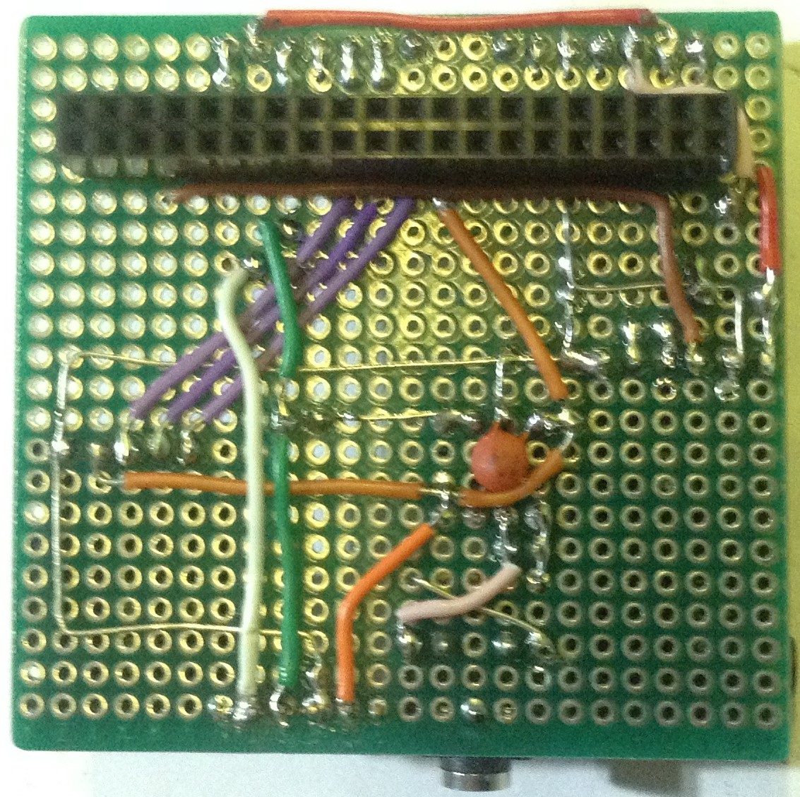
The Circuit

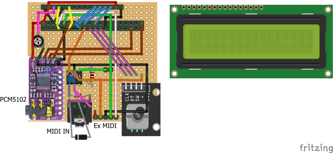
As the protoboard version isn’t that easy to follow, I’ve provided a schematic view too. This HAT provides the following:
- LCD screen with trim pot for the contrast.
- rotary encoder.
- PCM5102 I2S audio out.
- 3.5mm TRS serial MIDI socket.
- Breakout header for an external MIDI interface (with a jumper to disable the built-in MIDI link).
This is a very fiddly build, so I’m not going to even attempt to break it down into photos. In truth, if you’d like to build this, this is one of those cases where you’ll have to take my “design” (I’m being generous calling it that!) as inspiration rather than a recipe.
It is also worth at this stage thinking about if you want to add mounting holes to the board or not. I didn’t think about it until afterwards and don’t really have space near the GPIO header, and the board is too short on the bottom edge.
Note: this is using the GPIO pin arrangement as described in part 1. Also, if you make it without the PCM5102 and used a 26-way GPIO header socket, this could be used for a V1 (26-way GPIO) Pi too.
This is the order in which I did things:
- Fix on the GPIO header. I only soldered on two pins at this point – just enough to hold it in place whilst building the rest. Note its placement with respect to the edges of the protoboard. I’ve arranged things so that the LCD will overhang slightly.
- Fix on the 16-way header for the LCD, again, I’ve only fixed the two ends pins at this stage.
- Wire up the connections for the LCD and trim pot. The really tricky ones are the EN and RS connections (yellow) as these need to “cross” the GPIO header and we’ll need to solder to the pins the wires will be crossing later too.
- Test the LCD screen.
- If your encoder module comes with “right angle” pins installed, I recommend de-soldering these and replacing them with straight pins.
- Install the 6-way DIL socket.
- Install the rotary encoder.
- Optional: install the 5-way header pins for the external MIDI module.
- Connect the 3V3 connection and GND as far as the rotary encoder and optionally including the 5-way MIDI header.
- Connect the remaining three links for the rotary encoder.
- Test the encoder.
- Install the 3.5mm TRS socket and RX jumper.
- Build the MIDI IN circuit (opto-coupler, diode, two resistors, 3.5mm socket).
- Connect RX via the jumper to the MIDI IN circuit and the external MIDI header.
- Connect TX to the external MIDI header.
- Test the MIDI IN circuit.
- Install the PCM5102 and make the remaining connections.
- Test the PCM5102.
At each stage, it is always worth checking for shorts especially between 5V, 3V3, GND and between any adjacent GPIO connections. Soldering around RX/TX/EN/RS was especially tricky for me, so see how you go.
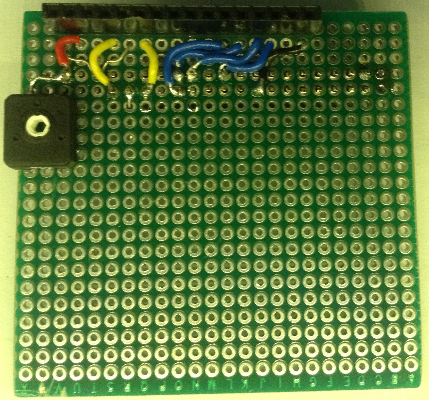
Here you can see the board once the LCD connection is complete.

I “doctored” my encoder module to change the pin headers to straight ones. An alternative option would be to use a bare encoder and either add pull-up resistors yourself or rely on the built-in pull-ups from the Pi. You could also add capacitors for some hardware debouncing too (it would seem that adding 10uF between each signal and ground does the trick- including for the switch). This is something I didn’t think about until afterwards and might go back and retro-fit.

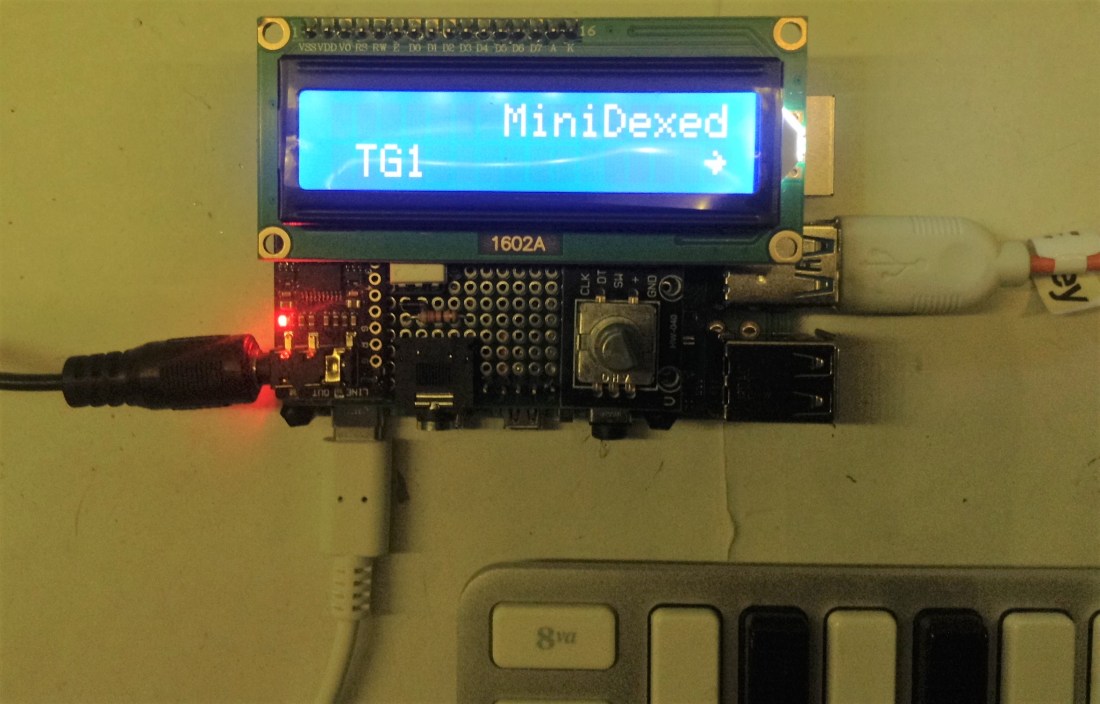
Finally here are some photos of the completed board.
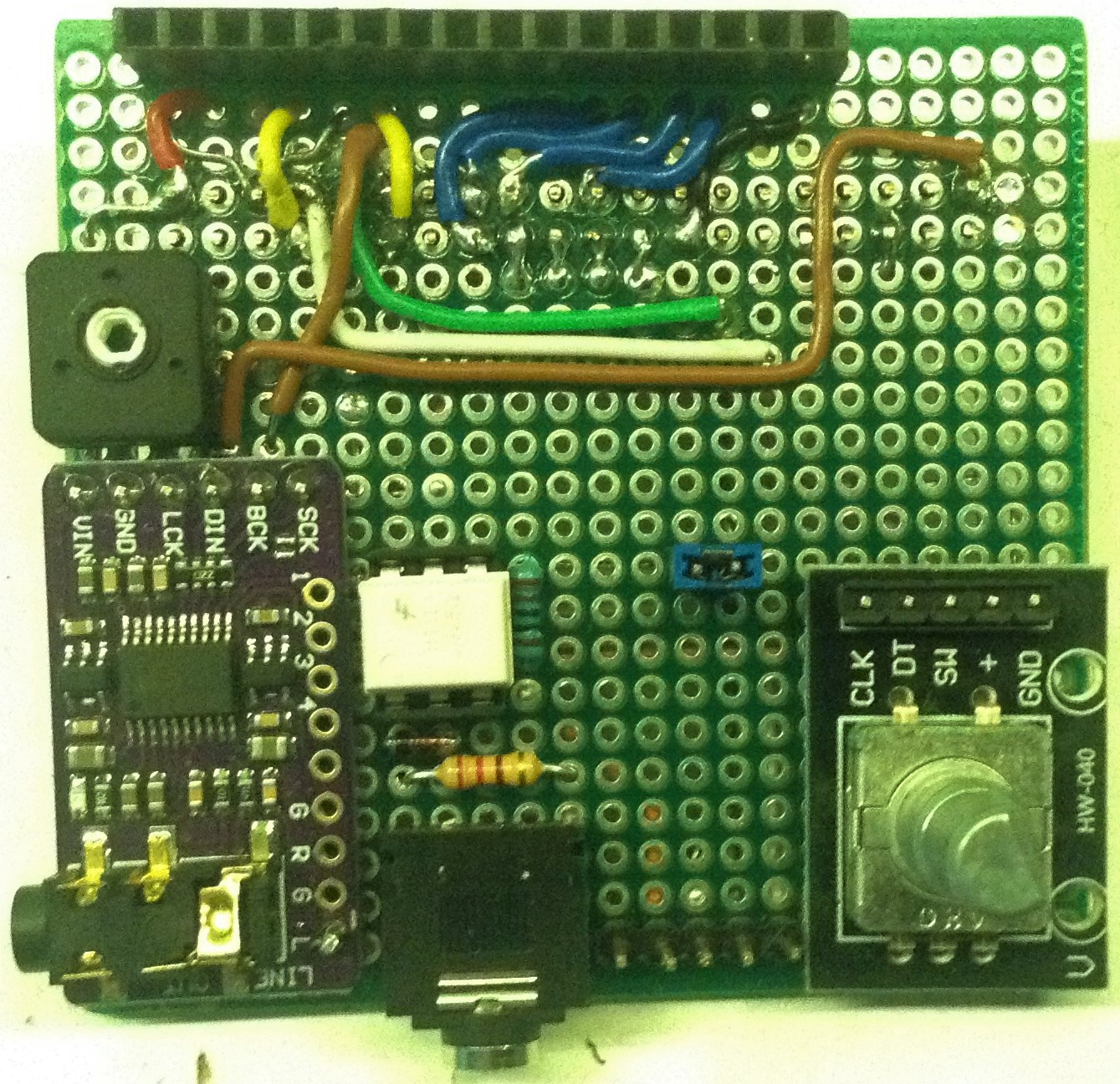
And with the LCD attached and plugged into a Raspberry Pi.

The Code
The code is as described in part 1. In particular, this is the minidexed configuration being used.
#
# minidexed.ini
#

# Sound device
SoundDevice=i2s
#SoundDevice=pwm
#SoundDevice=hdmi
SampleRate=48000
#ChunkSize=256
DACI2CAddress=0
ChannelsSwapped=0

# MIDI
MIDIBaudRate=31250
#MIDIThru=umidi1,ttyS1
MIDIRXProgramChange=1

# HD44780 LCD
LCDEnabled=1
LCDPinEnable=17
LCDPinRegisterSelect=4
LCDPinReadWrite=0
LCDPinData4=22
LCDPinData5=23
LCDPinData6=24
LCDPinData7=25

# KY-040 Rotary Encoder
EncoderEnabled=1
EncoderPinClock=10
EncoderPinData=9
EncoderPinSwitch=11

# Debug
MIDIDumpEnabled=0
ProfileEnabled=0
This allows by USB and serial MIDI input, but with no built-in THRU functionality, and is configured for an external I2S DAC.
Closing Thoughts
I’m pretty pleased with this. It was a right pain to solder all those GPIO connections, so this is really crying out for a custom PCB to be made to make it a lot easier and neater.
I did experiment with a range of different “proto HATs” for a Pi, but whilst they all made the GPIO part easier, none of the ones I had really had enough space in the right places for the other components.
Another thing I tried, was to separate out the LCD connection from the rest of the board. This made wiring it all up a lot easier, but it left the LCD raised significantly above everything else, so I abandoned that idea and went back to doing it all on the same board.
I only wish I’d thought about mounting! The whole thing works really well, but it is a little wobbly! It would also benefit from a neat case…
But for any serious use, the components would probably be directly mounted into a case and connected to a Pi with direct solder links to the GPIO, not via headers. I might see about a panel-mounted version at some point…
Kevin

It’s funny, I’ve gone down the same rabbit hole and built out a HAT, and found the lack of space a challenge. I’ve contemplated the capacitors on the rotary encoder as well to try and improve it (I’m using one that I salvaged from an old project and it’s a bit flaky). My LCD (also salvaged) is on the end of 10cm DuPont-style ribbon cables – they were 20cm F-F ones until I cut them in the middle and soldered them in place – and the homemade rotary encoder board is on regular 10cm leads, so that it can sit next to the LCD.
Your standard warning at the start of yours posts is very prescient though. The Pi 3B+ I was using died after I buggered up the wiring for the rotary encoder, and I shot 3.3V straight to ground when I pressed the button… ‘Fortunately’ it ‘only’ destroyed the Pi, not the DAC and LCD as well, so after a lot of swearing to myself I fixed it up and have it running on the unloved 1B I found at the bottom of a box of bits. (It’s now loved.)
LikeLiked by 1 person
Oh yes? Do you have a photo or a link? I’d like to see it 🙂
LikeLiked by 1 person
Have a look here: https://twindx.com/yamaha-dx-7-for-the-masses/ – both a photo AND a link!
LikeLiked by 2 people
Great! Sorry to hear (again) about your Pi 3, but an otherwise very entertaining writeup! 🙂
Aside – I was trying to find the maximum current you can draw from the GPIO of a Pi and I seem to remember it wasn’t obvious what it was, but the consensus is that it is quite a bit less than one might be used to with an Arduino… Presumably your 3B is completely dead now? I wonder if you’ve killed the chip or “just” something in the power circuit…
LikeLiked by 2 people
I think it’s probably completely dead, although I’ve contemplated bypassing the power circuitry and piping 3.3V straight into the GPIO header to see if it will nudge it in the right direction. I’ve got a spare Pi 2 and a cannibalised Pi 3 hanging around unused at the moment so if I need the extra oomph from some more cores I can fall back on one of them.
LikeLiked by 1 person