The last thing I wanted to do with my (dual) telephone ringer, well, besides trying to find six more phones and get an octave’s worth of ringing, was put my dual-ringer into a box. This shows how I managed that.
- In part 1 I talked about the basic hardware and approach.
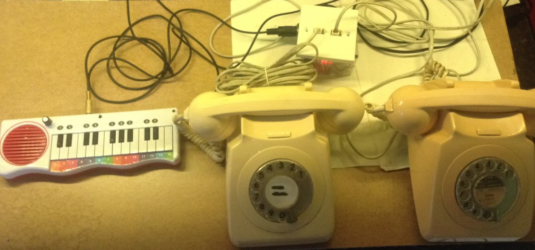
- In part 2 I added BT style sockets and upgraded the ringer to ring two phones.
Warning! I strongly recommend using old or second hand equipment for your experiments. I am not responsible for any damage to expensive instruments!
NEVER CONNECT ANYTHING DESCRIBED HERE TO A REAL PHONE SYSTEM AND BE VERY, VERY CAUTIOUS OF WORKING WITH THE VOLTAGES DESCRIBED HERE.
These are the key Arduino tutorials for the main concepts used in this project:
- Arduino MIDI Library
- Arduino Timer One Library
- Interface L298N DC Motor Driver Module with Arduino
- 250W Boost Converter Module DC 8.5V-48V to 10-50V
- Arduino Nano MIDI IN “Shield”
If you are new to Arduino, see the Getting Started pages.
Parts list
- Arduino Nano
- Arduino Nano MIDI IN “Shield”
- L298N “H Bridge” DC Motor Driver
- 250W Boost Converter Module DC 8.5-48V to 10-50V
- Two GPO 746 original vintage telephone
- Twin BT socket faceplate (with two independent connections for wiring)
- MIDI Interface
- MIDI controller
- Barrel jack socket
- SPST switch (for power)
- Chassis mounted 5-pin DIN socket
- 12V power supply
- Suitable box, mounting screws, connecting wires
The Circuit

This is effectively the same circuit as used in part 2, but with a couple of minor differences as follows:
- Most significantly this is using an Arduino Nano and my Arduino Nano MIDI IN “Shield” for the MIDI IN link.
- The four motor links are using D9 to D12.
- The Nano is powered directly from the 12V input via its VIN pin.
- The H-Bridge’s 5V comes from the Nano again, but in my case I used the 5V connection from the ICSP header as the 5V pin was already connected through to the MIDI shield.
- I’ve removed the two sets of screw terminals for the H-Bridge OUT ports, preferring to soldering wires directly to the pcb pads instead. I left the other screw terminals for power in case I had to remove it again in the future.
- It uses a twin BT socket faceplate with dual independent wiring connections (as shown).
I found an old “cotton bud” (“cotton swab” or “q tip” if you will) box that is pretty much the right size for the BT faceplate, so I’ve built the whole thing inside that. The main things to watch out for is to ensure that the connections are insulated, circuits fixed down, and movement of the components inside the box is minimal. I don’t know if the two heatsinks get particularly warm or not, but I’ve allowed for stand-offs and spacing around them just in case. I might need some ventilation in the box too, but I haven’t done that to start with.
Also the box is a little flimsy (I managed to crack it drilling a hole for the barrel jack socket… oh well).
Here are some photos of my build.


In general I’m pretty pleased with the result. It would be nice to find a better way to fix the faceplate onto the box, but a couple of ties does the job for now.
As the box is quite flimsy, I have to be pretty careful plugging anything into the 5 pin DIN socket. With hindsight, using a MIDI TRS jack socket might have been better.
The Code
This is using the same code as in part 2, but with four different IO pins for the H-Bridge:
#define HB_IN1 9
#define HB_IN2 10
#define HB_IN3 11
#define HB_IN4 12
Find the original on GitHub here.
Closing Thoughts
This is a nice place to park this project for now – all the components are in a relatively neat little box and it all functions as I’d like it to from a single 12V supply. For a “bit of fun” that will probably do for now on this one.
Kevin
