Having got the basics of “wireless MIDI” working with my nRF24L01 radios, I wanted to take advantage of the inherent “broadcast” nature of radio and see if I could transmit to a number of receivers at the same time. It turned out to be quite a bit more involved than I was expecting! But I got there in the end.
Read on for the full details.
Warning! I strongly recommend using old or second hand equipment for your experiments. I am not responsible for any damage to expensive instruments!
These are the key Arduino tutorials for the main concepts used in this project:
- nRF24L01 Interfacing with Arduino
- How nRF24L01+ Wireless Module works and Interface with Arduino
- NRF24L01 2.4GHz Radio/Wireless Transceiver Howto
- Arduino RF24 Library Examples
If you are new to Arduino, see the Getting Started pages.
Parts list
- 5x Arduino Uno, Nano, or similar
- 5x NRF24L01 radio modules
- 4x 8 ohm speaker or old headphone speaker
- 4x 220Ω resistor
- Optional: 4x LEDs with suitable resistor
- Arduino MIDI Interface
- Breadboard and jumper wires
The Circuit
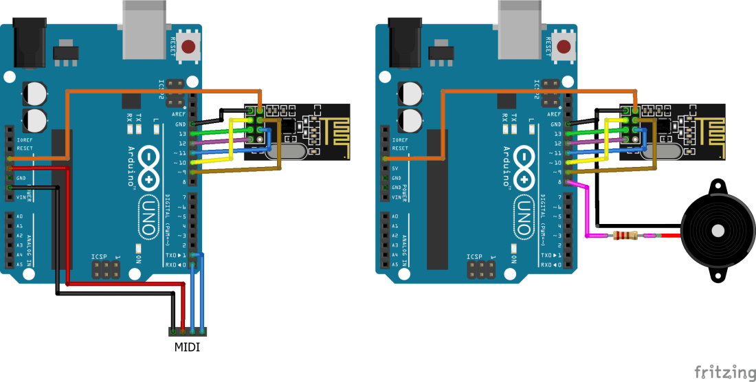
This is essentially the same circuit as before, but now I’m duplicating the speaker boards to give me four receiving nodes. Once again I’ve made use of my RF Nanos that have the nRF24L01 radios built in – see my last post on the topic for details.
One thing I thought was a useful addition was an LED. I can’t use the built-in LEDs on the Arduinos for indicators of MIDI activity as for ATmega328 based boards like the Uno and Nano they are connected to D13 which is now being used for the SPI interface to the radio. Instead I used an external LED and resistor connected to D4 and GND. Actually, I cheated slightly and set up D5 as an OUTPUT pin set to LOW to act as the ground connection for the LED so I could plug it into two adjacent pins. If you want to do that too you’ll need to add the code to drive D5 LOW too.
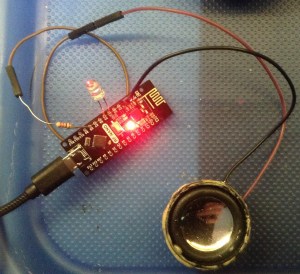
Aside: if you are really observant you might notice that the LEDs in my photos and video don’t appear to have a resistor… this is because they already have a resistor built-in! This is amazingly useful for something like this, but the downside is that they have to be “designed” for a specific voltage, in order to get the current limiting sensible. These are “5V ready” LEDs, which is ideal for this.
Actually the real downside of these LEDs is that there is no outward sign that these are “built-in resistor” LEDs! The only tell-tale was to note that they were a bit dimmer when driven from a coin cell (they are “optimised” for 5V not 3V) and checking the current draw with a meter!
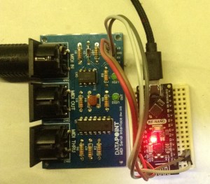
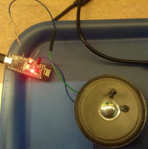
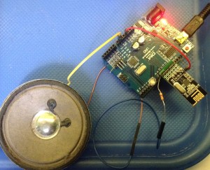
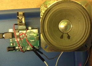
Here are some photos of my transmitter, with the serial MIDI interface, and my four receivers, each with a speaker (and resistor) attached.
Arduino Uno nRF24L01 Carrier Board
One thing I wanted to do was to reduce the number of cables when using the nRF24L01 with an Arduino Uno, so I designed this simple carrier board out of protoboard to house the radios and plug them directly into the Arduino’s headers. I toyed with various combinations of orientation of the carrier board vs orientation of the radios. You can see the options below.

The boards are designed to fit between D9 and D13 + GND via a 6-pin header. But they also need a power link. This has to come from the 3V3 header on the other side of the Uno so it needs a single “power” jumper wire adding.
In the end I opted for the following setup. I’ve used two 4-way female headers with one offset by one. The 8th pin of the nRF24L01 isn’t used, but it means I can expose the 3V3 pin on the module directly to a spare header slot and plug a jumper wire in between that and the 3V3 header on the Uno.
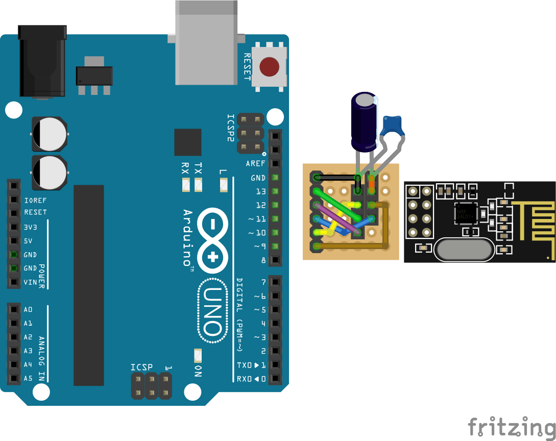
I’ve also allowed for the possibility of adding some capacitors across the power lines for the radio modules. General wisdom on the Internet seems to be that when using these modules from an Uno’s 3V3 supply directly it is well worth adding a 10uF capacitor to help stabilise the power supply. This turned out to be pretty critical for me later on!
Here is my finished carrier board (minus the capacitor – I added that later on the underside of the board). I made two of them.


The Code
My key aim for this project was to get the MIDI data to several receivers as efficiently as possible, ideally with a single radio broadcast out to all listening nodes.
RF24 Broadcasts
As the RF24 radio protocol has the concept of an “address” for a sender and receiver, then in principle if all receivers are listening for the same address, they will all receive the data being sent at the same time.
Well that can sort of be done, but there is a problem. As the protocol used by the nRF24L01 radios is designed for reliable transmissions, it includes the option for built-in acknowledgements of the sent data, with automatic resending of data for any failed transfers. This makes things nice and simple when sending data between specific nodes, but leaves a problem if you want to send to all nodes at the same time.
As soon as a node receives the data it will return an acknowledgement back to the sender. But if all nodes receive the data at the same time they will all try to return acknowledgements which results in on-air data collisions and failures, causing resending, causing more problems, and so on. In short you get all sorts of weird behaviour going on and it is useless for any real use for MIDI.
The answer for the broadcast scenario is to disable automatic acknowledgements. This can be done using the function:
mRF24.setAutoAck(0);
When the radio is first initialised. This restores the timings of the MIDI stream but now the transmissions are unreliable – if data is corrupted or otherwise lost (as will often happen in radio communications) then the receiver will only receive partial or lost MIDI messages, resulting in stuttered playback.
The solution to this would be to implement some kind of manual “multiple sending/retrying” mechanism over the top of the nRF24 radio layers, so I didn’t take this any further for the time being.
RF24 Multicasts
Instead, I cheated a little and opted for a “multi-cast” model. With this kind of model, I’m implementing a manual “multiple sending” of each piece of data to all nodes “by hand”. The basic idea is as follows:
- Tell the RF24MIDI layer how many receivers there will be.
- Tell the RF24MIDI layer the base address to use.
- Configure all receivers to listen on different, consecutive addresses.
- Whenever there is data to be sent, send it to the base address and then also to all additional receivers, assuming they will be on consecutive addresses.
This isn’t taking advantage of the true broadcast nature of radio communications as I’m having to send the data several times – once to each receiver. But ultimately if you want to know that every node has received your data, then you need something more intelligent than “fire it out to anyone listening nearby” anyway.
This did not go smoothly however, as there are a number of “gotchas” associated with nRF24L01 radio addressing, pipes and hardware stability. The main considerations (that I mostly found by lots of trial and error, then more reading and re-reading of tutorials and datasheets, then searching for more obscure information in the code until I found more clues…) are:
- Most of the tutorials for multiple radios assume a single listener and up to six transmitters. This is great for a coordinating “central sensor node” type arrangement, but I wanted to do the opposite – one transmitter and many receivers! Consequently, the clever “multiceiver” mode described in many places online doesn’t help me here.
- Following on from that, the idea of multiple listening pipes is redundant for this use-case. I initially thought you’d need a listening pipe for each node you’re transmitting to (for the acknowledgements) but this isn’t actually the case – see next point.
- Some tutorials talk about “writing to pipe 0” and “reading from pipe 1” but don’t really talk about why. It turns out there is a really, really good reason why. Even though all six pipes can be used as receivers, pipe 0 is special as the driver code “takes it over” when transmitting so that it can receive the acknowledgements back from the receivers, so really, it is a very good idea not to use pipe 0 for your own purposes.
- So whilst the openReadingPipe() function takes a parameter indicating which pipe to attach an address to, and can support six open read pipes at once, the openWritingPipe() function does not. There can only be one open write pipe at a time so it has to be re-opened if you want to send to multiple addresses.
- There are lots more notes and caveats due to addressing and pipes, and I won’t go into more detail now, but you can read more about it here and here.
- Even when everything is working, you might still get unreliability issues. After exhausting all software options (which has taken me something like 4 to 5 elapsed days already) I eventually remembered the comments about adding capacitors, so I added them to my carrier boards and amazingly, well, you can hear the results in the video! It worked!
In order to configure a relay module for broadcasting to several receivers, I’ve added a new configuration macro to the RF24MIDI library for “broadcast” uses:
#define RF24MIDIBROADCAST 3
#define RF24MIDIINADDR  0x30
#define RF24MIDIOUTADDR 0x31
RF24MIDI_CREATE_BROADCAST_INSTANCE(RF24MIDIINADDR, RF24MIDIOUTADDR, RF24MIDIBROADCAST, RF24MIDI);
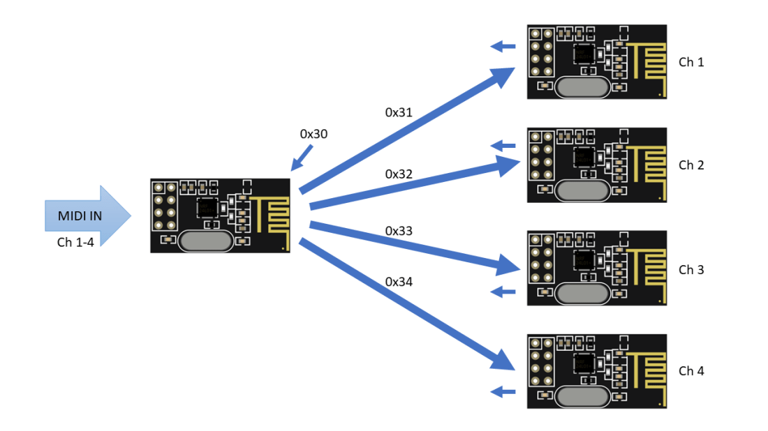
This will configure the base OUT address and then automatically transmit to the three following addresses – so 0x31, 0x32, 0x33, 0x34 in the above example (which handily for debugging purposes correspond to the ASCII characters “1”, “2”, “3”, and “4”).
RF24MIDI Tone Module
The receiving code is a variation on my previous Arduino tone projects. This will listen on a single MIDI channel using the RF24MIDI link and play a tone for any received MIDI NoteOn messages.
The addresses used are configured as follows:
- Relaying Transmitter: Sends on addresses 0x31, 0x32, 0x33, 0x34. Listens on address 0x30 (although this is unused).
- Tone Module Receivers: Listens on one of the addresses: 0x31 to 0x34. Sends on address 0x30 (although this is unused).
In the code, the address used is linked to the MIDI channel, although it doesn’t have to be. This means that just changing the MIDI channel will automatically also change the address thanks to the following code:
#define MIDI_CHANNEL 1
#define RF24MIDIINADDR  0x31
#define RF24MIDIOUTADDR 0x30
RF24MIDI_CREATE_INSTANCE(RF24MIDIINADDR+MIDI_CHANNEL-1, RF24MIDIOUTADDR, RF24MIDI);
The addressing scheme is illustrated below.
Both these sketches are now provided as examples in the GitHub repository.
Closing Thoughts
This was a lot more involved than I thought it would be! There are still some serious limitations too. If a node is missing or you’ve configured more receivers than actually exist then the transmissions will start to stutter and become unreliable as timeouts and retries start to occur.
There are some circumstances where I could imagine the “true” (non-acknowledged) broadcast mode might be useful. One example might be in continuous streaming of MIDI continuous controller (CC) messages. But it would have to be more cognisant of actual MIDI messages than it is at the moment.
At present, it is still sending single bytes in each radio “packet” which is quite inefficient. Ideally it would be sending a complete MIDI message, which is typically either two or three bytes for most messages. I think I can add some intelligence into the transport driver to make it store bytes until it has a complete message, but this breaks the neat layering of the MIDI library. But it would make a lot more sense.
It is also sending all bytes to all four receivers, even though I’ve configured it so that each receiver is only listening to a single MIDI channel. This means that the transmitter sends MIDI channel 1 data to all four nodes, even though only one will act on it. One option here would be to allow several instances of the RF24MIDI object with the correct channel configured rather than using the “broadcast/multicast” mode, but all instances would still have to work on the same underlying RF24 library layer.
But regardless of all this, it does seem to be largely working.
Moving forward, I wondering of the “multi-ceiver” mode could be used as a kind of “radio MIDI merge” but I’m not sure there would be a real use-case for it.
One thing I would still like to try is the USB nRF24L01 module I have, to see if I could drive the whole thing from a PC directly and I’d still like to explore other microcontrollers.
This is still very much early experimental code though and there will be massive holes in the implementation and use! I’m still mindful of the following quote I found recently:
“Look, I’m not going to say you can’t do wireless or networked midi. You definitely can. It’s just that there’s alway something that goes wrong.”
Kevin
