A while back I bought some cheap slider potentiometers, so decided to get them out and give them a go. This first project is using eight with an Arduino Nano as a multi-slider MIDI controller, expanding on my Arduino Simple MIDI Controller.
- In part 2, I show a version that uses a multiplexer.
- In part 3, I extend it to 16 potentiometers.
- And here are some other projects using the resulting board:

Warning! I strongly recommend using old or second hand equipment for your experiments. I am not responsible for any damage to expensive instruments!
These are the key Arduino tutorials for the main concepts used in this project:
If you are new to Arduino, see the Getting Started pages.
Parts list
- Arduino Nano
- Up to 8 10k linear (“slider” or “fader”) potentiometers
- 42×30 protoboard
- Male and female headers
- Connecting wires
- MIDI interface with IN and OUT (for example one of the Ready-Made MIDI Modules)
- Breadboard and jumper wires (optional, not recommended)
The Circuit
My fader/slider pots have four pins at the top and two at the bottom and are arranged as I’ve tried to show in the small diagram on the left (as seen from the top). Each pot is essentially two sliders in one with pins at the top and bottom encompassing the entire 10k range and an additional “wiper” or “fader” pin at the top. You can see more of what I mean in the photo below, where I’ve drawn out the equivalent circuit from the bottom too.

For what I need, I’ll only be using one side of the potentiometer, so I’ll only need two pins from the top and one from the bottom. I’ve used eight alongside each other in the arrangement shown above. This was just too fiddly for me to attempt on solderless breadboard, so I went straight to proto-board.
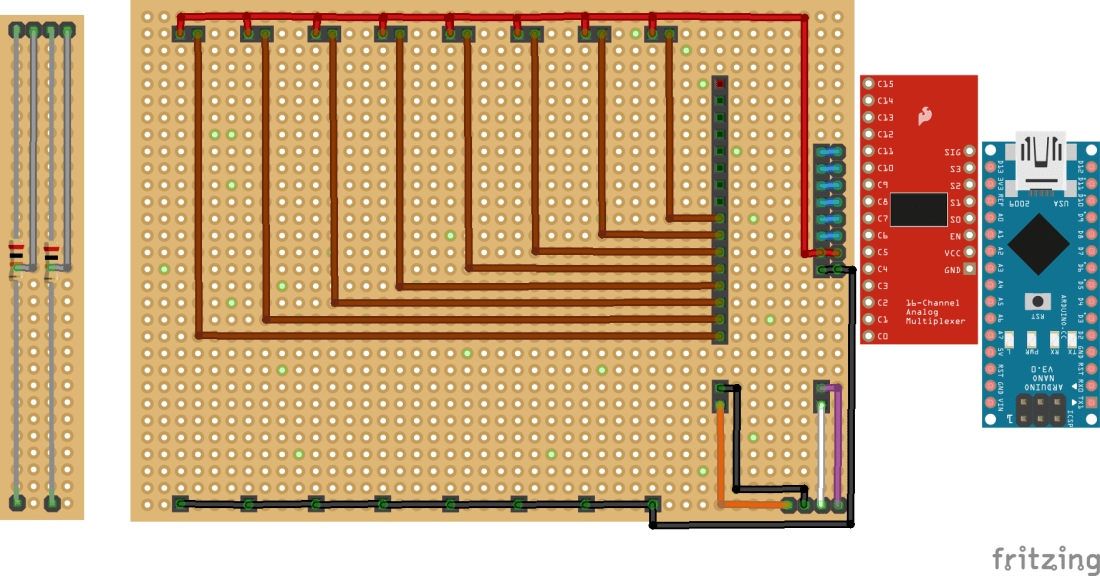
I want to be able to use this with one of my 74HC4067, 16-way analog multiplexer modules (more here) so I’ve used a header arrangement that will allow me to plug one in later.
But for initial testing, as I have eight pots, I thought I could use the eight analog inputs on an Arduino Nano directly instead. These are all situated side-by-side on a Nano, so I decided to add a couple of extra pin headers to allow the Nano’s analog pins to line up header wise with the first eight inputs of the mux.
There are a couple of quirks to watch out for doing this though:
- The Nano will overlap three pins (AREF, 3.3V, D13) with the rest of the mux’s inputs, but this is not an issue as they aren’t being used.
- The Nano will also plug into the mux’s other header too, but the only things that are needed on this side to be used are the VCC and GND links to the pots. One easy way to cope with this is to use the two digital IO pins on the Nano that plug into the VCC and GND links as HIGH and LOW digital outputs to simulate the VCC and GND connections. So that is what I’m doing.
One additional thing I want to support is a MIDI connection, so I’ve routed the Nano’s RX, TX, VIN (it was nearer than VCC), and GND to a four-way header for a MIDI interface shown in the bottom right of the Fritzing diagram.
Although this is a MIDI controller, so it will be sending MIDI data OUT, the thing being controlled is highly likely to have other controllers (e.g. a keyboard) plugged in, so I’ve wired up both RX and TX to give me MIDI IN and MIDI OUT to enable me to use the Arduino MIDI Library’s built-in MIDI THRU functionality.
One thing to note: the voltage on the digital IO pins of an Arduino Uno is always slightly less than the actual VCC power supply voltage. This means that using an IO pin as the analog reference means it will never quite get a full range reading from the analog input pin. But that is relatively easy to cope with in software.
It was also a bit of a cheat to use the VIN pin to power the MIDI interface, but it was slightly simpler than routing up to the 5V pin. When powered from USB, VIN is 5V anyway.
Here are some photos of the build. Starting with the 42×30 protoboard, you can see I’ve used a whole sheet. My sliders had mounting lugs in addition to the pins and whilst I initially wondered about simply folding them under, I decided they ought to be used for support, so ended up drilling some holes in the protoboard to take them.
Note that the dimensions of my faders mean that their pins are in the bottom row of the protoboard and the top-but-one one. This is reflected in the fact that the mounting holes for the lugs are one row further in from the top compared to the bottom.


Once the pots were in place and soldered down, the headers were added and then wired up.


Here is the multiplexer mounted. Note that this configuration is, at the time of writing, untested. Watch this space!

And here is the Arduino Nano in place. Recall that IO pins 6 and 7 will be acting as GND and VCC for the pots respectively.

The Code
The code is a variation on the Arduino Simple MIDI Controller. The key differences being:
- I need an array of eight pin numbers for the analog inputs. I could have calculated these if they were always going to be consecutive, but using an array gives the maximum flexibility for the future.
- I need an array of eight MIDI CC messages to use corresponding to each pot.
- I need to include MIDI.read() in order for the MIDI library to perform its software THRU functionality.
- To keep the MIDI handling responsive, I only scan one potentiometer at a time.
- As mentioned above, the analog reference voltage is not quite full-range when powered from an IO pin so some slight scaling of the analog readings are required to get the full 0 to 127 range for the MIDI controllers.
Closing Thoughts
This is a good first stage and the controller seems to work fine. Next up will be a version of the same functionality but using the multiplexer which paves the way for an additional eight pots for a more complex unit.
Kevin
