There have been a number of occasions now where I’ve added a low-pass filter and voltage divider to my Arduino-based PWM outputs so I thought it was worth pulling that together into a single post to make it easy to refer to elsewhere. This is that post. There is nothing new here, it is just documenting things I’ve done elsewhere.
In part 2, I build the same circuit onto a proto shield.
Warning! I strongly recommend using old or second hand equipment for your experiments. I am not responsible for any damage to expensive instruments!
These are the key previous projects for the main concepts used in this project:
If you are new to Arduino, see the Getting Started pages.
Parts list
- 1x 1.5K resistor (was 270Ω)*
- 1x 330Ω resistor (was 75Ω)*
- 1x 68nF capacitor
- 1x 10uF non-polar capacitor
- Breadboard and jumper wires
* See discussion below.
The Circuit
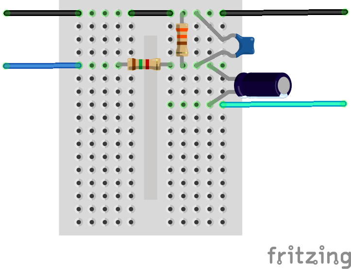

The original Mozzi Output Circuit used a 100nF capacitor and a 270Ω which gives a roll-off frequency of just under 6kHz. Using a 68nF capacitor ought to push that up to around 9kHz (see more here).
I want to also drop the voltage down to a more audio friendly level and add a coupling capacitor, so my initial attempt introduced a potential divider using the 270Ω resistor from the Mozzi circuit and an additional 75Ω resistor to GND.
But including a potential divider changes the properties of the filter too. A very hand-wavy (for me, I don’t follow the theory) way to think about it is to treat the potential divider as its Thevenin equivalent resistance. It (apparently) can be shown that the equivalent resistance for a potential divider can be considered to be the same as if the two resistors were in parallel.
This means, that for filter calculation purposes, the “R” in the filter is actually equal to:
R = R1 * R2 / (R1 + R2)
In the case of the my original values, that comes to around 58Ω. Plugging that into a filter calculation gives a roll-off frequency (at the 3db point) of almost 40 KHz! That won’t filter out the PWM carrier frequency at all.
For a voltage reduction to around 20% (i.e. from 5V peak to around 1V peak) requires: R1 = 4 * R2, so to get an equivalent resistance of 270Ω whilst giving the required reduction, we can link the two equations together:
R = (4 * R2) * R2 / ((4 * R2) + R2) = 4 * R2 * R2 / (5 * R2) = 4 * R2 / 5
So 270 = 4 * R2 / 5 which means that R2 = 5 * 270 / 4 = 338Ω and therefore R1 = 1350Ω.
I have 330Ω and 1.5K resistors in my parts box, so I’m using those which is around 270.5Ω combined resistance and around a voltage reduction down to around 18%.
This is working on the assumption of a 0-5V input PWM like signal.
Recall that I’m not an “electronics person”, so treat this as a work in progress at best, but it seems to do the trick for me. I get a much nicer signal out of my PWM now at a much more useful voltage.
Kevin


One thought on “Arduino PWM Output Filter Circuit”