This project goes back to the LOLShield and uses it to trigger some LED animations in response to MIDI events.
Warning! I strongly recommend using an old or second hand keyboard for your MIDI experiments. I am not responsible for any damage to expensive instruments!
These are the key Arduino tutorials for the main concepts used in this project:
If you are new to Arduino, see the Getting Started pages.
Parts list
- Arduino Uno
- LOLShield (these are readily available on ebay)
- MIDI In circuit (see Arduino MIDI Interfaces)
- Jumper wires
The Circuit
If you don’t have one already, you’ll need to build a LOLShield following the details from my previous project. Note that for this you only need one LOLShield directly connected to the Arduino.
To add MIDI, once again the tricky part is getting access to some pins while the LOLShield is in place. However it doesn’t use the TX/RX pins so you have a number of options:
- Something like my USBMIDI to MIDI Shield could work if you want to drive it using a USB device.
- If you want to drive it from a PC directly, then you could add something like my PC USB to Arduino Serial MIDI shield.
As I have some Arduino Uno clones lying around with additional breakouts on the board for the UART, I’m using one of those with some extra pins soldered on as shown below.

This allows me to use my Simple USB-MIDI to MIDI from Hobbytronics and my Korg Minikeys.

The Code
The MIDI handling is relatively straight forward and pretty much the same as my other projects.
The software side of talking to the LOLShield has handled by the LOLShield library (I covered the installation before here).
The key issues to be addressed in this code therefore were:
- Encoding and storing “animations” to be played on the LEDs.
- Creating a means to playback different frames from each animation.
- Linking the triggering of animations to specific MIDI notes.
My approach to the last two was to encode the idea of a “current playing animation” which can be changed in response to different MIDI notes being received then in the main loop() have it draw a frame from the animation onto the LED matrix at a set interval and then advance onto the next frame.
To get a sensible animation speed, I use the millis() function to record the time for displaying one frame and then wait a short amount of time before showing the next frame.
t_now = millis();
if ((t_now-t_last) >= ANIMATIONSCAN) {
  t_last = t_now;
  // Show the next frame
}
To encode the animations, I essentially need a bit pattern to describe which LEDs to turn on and off for each frame of the animations. As the LOLSheild is a 14×9 display, I can encode each frame as 9 uint16_t values – with each 16-bit value defining the 14 LEDs in a single row – so 9 rows required in total per frame.
Ideally if a new animation is to be triggered it would play out on top of any existing animation, but that requires a more complex understanding of “layers” in the graphics that I don’t want to get involved with. So instead I have two choices – either wait for an animation to finish before triggering a new one or interrupt any current playing animation with the new one. I opted for the latter which just makes the whole thing a lot more responsive. Consequently there is a “trigger” in the code, set when the right Note On message is received, that will reset the animation frame counter back to zero and clear the screen ready to start playing the newly selected animation.
There are two play modes:
- Normal – where there is an animation linked to a specific MIDI note message.
- Random – where any of the listed MIDI notes will trigger any of the stored animations at random. This uses the arduino random() function, which isn’t truly random in the strict mathematical sense of the word, but is random enough for our purposes.
The mode is chosen by including or commenting out the RANDOMANIMATION definition near the top of the file.
There is also a test mode that simply cycles through all stored animations without requiring MIDI input.
Having more than a couple of animations will start to eat into the memory of the Arduino pretty quickly, so the animations should be stored as const PROGMEM values (as we’ve done before). I use a three-dimensional array to store bit-patterns as rows per frame, with frames per animation, with multiple animations.
This is illustrated below with animations enclosed in an outer set of curly brackets { }, containing several frames each within their own set of { }, each containing 9 16-bit values containing the data for each row in the frame.
#define ANIMATIONS 2
#define ANIFRAMES  3
#define ANIROWS    9
const uint16_t PROGMEM ani[ANIMATIONS][ANIFRAMES][ANIROWS] = {
  { // First animation
    { // First frame
        // 9 16-bit binary values per frame
    },
    { // Second frame
       // 9 16-bit binary values per frame
    },
    { // Third frame
       // 9 16-bit binary values per frame
    },
  }, // End of first animation
  { // Second animation
     { // etc
     }
  }, // End of second animation
};
I use the binary notation to specify each value (0B0000111100001111) and initially was drawing out single bits “by hand” in each frame, which is an ok way to do it. But after a bit of hunting around, I found “Maximum Octopus LED Matrix Studio” which allows you to draw individual frames for an LED matrix animation and then animate them, which is great. You can find it here – http://maximumoctopus.com/electronics/builder.htm
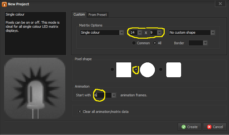
When you create a new project, you can define that you want a 14×9 matrix (to match the LOLSheild), you can set the initial number of animation frames (I’ve used 6) and the shape of the LEDs (I preferred circles).
When creating animations, I found the “light box” really useful to show a “ghost” of the previous frame’s LEDs. This can be found at the far right of the tool-bar at the bottom of the screen with all the “play/forward/back” type buttons.

I used the tool to create a single set of frames for one animation and then used the “export” function to output code I could use with the Arduino.
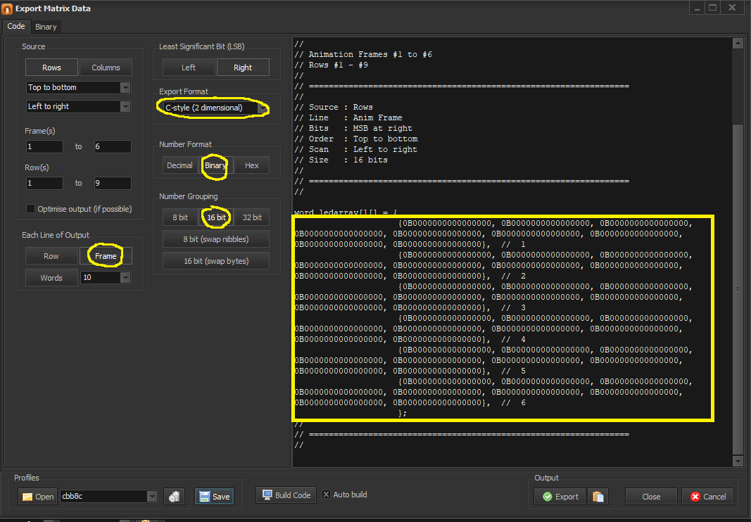
This can then be copied out and pasted directly into your sketch.
{ // One single Animation
 {0B0000000000000000, 0B0000000000000000, 0B0000000000000000, 0B0000000000000000, 0B0000000000000000, 0B0000000000000000, 0B0000000000000000, 0B0000000000000000, 0B0000000000000000}, // 1
{0B0000000000000000, 0B0000000000000000, 0B0000000000000000, 0B0000000000000000, 0B0000000000000000, 0B0000000000000000, 0B0000000000000000, 0B0000000000000000, 0B0000000000000000}, // 2
{0B0000000000000000, 0B0000000000000000, 0B0000000000000000, 0B0000000000000000, 0B0000000000000000, 0B0000000000000000, 0B0000000000000000, 0B0000000000000000, 0B0000000000000000}, // 3
{0B0000000000000000, 0B0000000000000000, 0B0000000000000000, 0B0000000000000000, 0B0000000000000000, 0B0000000000000000, 0B0000000000000000, 0B0000000000000000, 0B0000000000000000}, // 4
{0B0000000000000000, 0B0000000000000000, 0B0000000000000000, 0B0000000000000000, 0B0000000000000000, 0B0000000000000000, 0B0000000000000000, 0B0000000000000000, 0B0000000000000000}, // 5
{0B0000000000000000, 0B0000000000000000, 0B0000000000000000, 0B0000000000000000, 0B0000000000000000, 0B0000000000000000, 0B0000000000000000, 0B0000000000000000, 0B0000000000000000}, // 6
} // End of this animation
Then do the same for any other animations you care to define.
Closing Thoughts
I’m really pleased with how this has turned out, and finding the LED Matrix Studio has made it a lot easier to work on. I did wonder if there were any ready made animations out there on the Internet, but my initial searching didn’t uncover anything particularly interesting.
I might now programme this into several Arduino and LOLShield combinations and see how I get on.
I’ve also got a few Ciseco “Pi-Lites” which unfortunately aren’t readily available anymore but are essentially an Arduino+LOLSheild combination in the form factor of a Raspberry Pi add-on. Used on their own, they could easily be made to run the above code and would give me a few interesting possibilities for different effects in a stand-alone unit.
Kevin
