The simple Mozzi Output Circuit is fine for experimenting but when it comes to combining signals it can really do some damage – I may have trashed the small amp I was using for my experiments – remember my warning – I strongly recommend using an old or second hand keyboard for your MIDI experiments. I am not responsible for any damage to expensive instruments!
One of the issues is that the signal from the Arduino swings between 0 and 5V. A normal line-level audio output signal is typically between -0.5V and +0.5V for consumer equipment and -1.7V and +1.7V for “pro” so it is easy to overload anything you connect up to your Arduino.
Adafruit have published a great tutorial for how to get a decent audio out signal from a Raspberry Pi, so I adapted their circuit a little and combined it with the Mozzi output circuit. This is the result.
These are the key tutorials for the main concepts used in this project:
Once again, if you know about soldering, this is not an advanced project, but if you are new to soldering, then I would recommend that you find some tutorials on the Internet to get you started soldering first.
Parts list
- Protoboard
- 1x 270Ω resistor (1.5K might be better – see discussion below)
- 1x 75Ω resistor (330Ω might be better – see discussion below)
- 1x 100nF capacitor
- 1x 10uF non-polar capacitor
- 3.5mm stereo jack socket
- Jumper wires and headers as required
The Circuit
Update: See discussion later on about some better values to be using…

Ignore the component numbering! R6 and R7 make a potential divider so that that output voltage across R7 can be calculated as follows:
Vout = 5V * R7 / (R6 + R7)
Vout = 5 * 75 / (270 + 75)
Vout = 1.09
This means that for an input voltage in the range 0 to 5V, the peak output voltage will swing between 0 and around 1.1V or +/- 0.55V when the bias is removed (see later) which should be largely ok for consumer audio style applications (according to Wikipedia).
I could possibly have used a 180Ω resistor for R7 which would give me a Vout of 2V which would make for a larger +/- 1V signal once the bias is removed… If you want to do your own experimenting, see: https://ohmslawcalculator.com/voltage-divider-calculator.
R6 and C6 are chosen to provide the cut-off frequency for the low-pass filter as described in the Mozzi output tutorial:
freq = 1 / (2πRC)
freq = 1 / (2π * 270 * 0.0000001)
freq = 5894.6
This means that this filters out any frequencies above almost 6 kHz. Once again feel free to experiment with different values. See: http://sim.okawa-denshi.jp/en/PWMtool.php.
Finally the 10uF capacitor (C8) blocks the DC offset of the voltage so that instead of swinging between 0 and some maximum it now swings between +/- that maximum/2. Using my original values that means a -0.55V to +0.55V signal.
Note all this is a rather simplistic discussion, provided with the caveat that I’m not an electronics person – I think this is what is happening, but do your own research to check! I’ve not even considered circuit impedance, so the Warning! still applies – it work for me, that’s all I can say.
Discussion Update
I was never really happy with how the potential divider was messing up the filter, but it seemed to work enough for what I needed so didn’t worry about it.
However, I’ve now attempted to read up a bit more on my electronic circuit theory to see what is really going on when a potential divider is combined with a low-pass filter, and I believe the best way to consider it is to use the Thevenin equivalent of the potential divider as the resistance in the filter calculation.
From what I can gather the Thevenin equivalent resistance is the same as if the two resistors were in parallel, so
Rth = (R6 * R7) / (R6 + R7)
So, I want Rth to be 270Ω with C being 100nF whilst at the same time requiring R6 = 4 * R7 to give a 5:1 voltage reduction.
So the calculation goes something like this:
270 = (R6 * R7) / (R6 + R7) = (4 * R7 * R7) / (4*R7 + R7) = 4 * R7 * R7 / (5 * R7) = 4 * R7 / 5
So R7 = 270 * 5 / 4 = 338Ω, which means R6 = 1350Ω.
So a better resistor selection would be (using nearest common values) something like 330Ω and 1.5K (or thereabouts).
Using the Thevenin equivalent for the 270Ω and 75Ω values, gives a resistance of ~58Ω which would give a filter cut-off of around 27kHz…
To be honest, I’m still not entirely sure I’ve got the final answer even now. There is also a coupling capacitor in there to consider too… so again, I’m probably still talking rubbish!
End of Update!
Once again I’ve built two versions one for the Arduino Uno and one for the Arduino Nano to have a simple module that connects directly to D9 and GND on the Arduino that I can plug a stereo jack lead directly into.
Arduino Uno Version
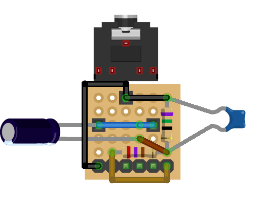
Note that the circuit shows a normal electrolytic 10uF capacitor, but the circuit calls for a non-polar capacitor, so it doesn’t matter which way round it goes.
Here are some of the build stages for my version – note it doesn’t follow the above exactly – as with all these things you change your mind as you start putting components together!


Arduino Nano Version

Once again the capacitor is shown as an electrolytic, but use a non-polar one, so the orientation doesn’t matter.
In the following diagrams you might notice that I’ve use a proto board with three extra short rows – this allows me to breakout the RX/TX signals as well on the Nano which will be useful later when hooking it up to MIDI.


Closing Thoughts
As I said before, having simple ready to go modules like this makes experimenting a lot easier. I don’t know why AC coupling isn’t included in the standard tutorials for Mozzi, but removing the DC offset and scaling the voltage to more reasonable levels makes a significant difference when it comes to mixing signals later on.
Kevin
