Recently I’ve started detailing the design and build process for a number of projects based on custom designed (by me) and made (using a PCB fabrication service) printed circuit boards. As with all my projects, the design files are usually published to GitHub and you can find them all here: https://github.com/diyelectromusic/sdemp_pcbs
This page gives some details of what to do if you’d like to use my designs yourself, with some additional context that you should consider before you do.
To see all my PCB projects, use the PCB Design Category on the blog, but there is a high-level summary at the end of this post.
I Don’t Sell PCBs
First things first – sorry, you can’t buy a PCB from me. But they are relatively straight forward to get ordered in small numbers if you want to get hold of one.
And if you want to ping me an email or jump in on the Discord channel, I’d be happy to help walk you through the process of getting one built. In general terms, my PCBs are relatively simple designs and almost always the default options offered by the PCB manufacturer will be fine which means the process is usually:
- Read my design and build notes taking particular care over any errata I’ve identified and any other comments I’ve made.
- Remember, I don’t consider myself an electronics person, so at best these are DIY prototypes and you should expect to spend some time tailoring, testing and debugging!
- Grab the ZIP file of gerber files from GitHub.
- Upload it to the PCB manufacturer of your choice (or use pcbshopper to try a few).
- Accept the default choices.
- Select a suitable postage option for you.
- If the cost seems reasonable, go for it.
For more details, see “Getting a PCB Built” below.
Important Context
I consider myself still a novice at PCB design and I am still learning as I go. My followers have been great at getting me up and running and there is a lot of information out there for PCB design using the open source KiCad which I can totally recommend.
My first project, with details of what I had to work out to get going to take a protoboard design to a PCB, can be found here: Arduino Uno Dual Merge MIDI “Shield” – Part 2.
So with all this in mind, please treat all my designs as follows:
- They are prototypes not products. They are published in the spirit of giving someone else a starting point for a DIY project based on what I’ve been able to pick up, but you should expect to have to evaluate the design and build and debug it yourself. If you are not comfortable with doing that then these are not for you.
- Like my electronics, I consider myself to know enough “to be dangerous” and am wary of riding up the “mount stupid” curve at present. So these designs will have a lot of “I don’t know what I don’t know” in them and I expect that if I continue to learn, I’ll one day look back on some of these and cringe.
- I tend to be pretty free with my choice of components and as far as my ignorance is telling me, I don’t think my projects rely on any specific variant of component unless otherwise stated (but see my other comment about my electronics knowledge). Check the design and build notes for details of any specific footprints I’m assuming in the design of the PCB. As a rule, I’ve only tried to use through-hole components.
- As with all my projects, please don’t use them with expensive equipment you can’t afford to break. I cannot recommend enough the use of free, cheap or second hand equipment for testing DIY music projects.
- Ultimately only use these designs after your own detailed assessment and review and then totally at your own risk.
I’m very happy to help out if I can answering queries about them in the comments, via social media, or perhaps most usefully for a discussion, on my Discord channel.
Getting a PCB Built
All my published PCB designs can be found on GitHub here.
They are published with the following:
- A readme with important context, links to the design and build blogs, a bill of materials, and any errata or workarounds that you should be aware of before ordering or building.
- A Schematic.
- A complete set of Gerber and drill files (basically what you’ll need to get one built yourself) both individually and in a combined ZIP file for convenience.
There is nothing special about most of the projects that means that they can’t be built with most of the default options from a PCB manufacturer. If I can keep the PCB to within a 100x100mm footprint then I will as this tends to be the cheapest option to build, but occasionally some are larger, so check prior to ordering.
The basic procedure is as follows:
- Read through the design notes and make sure you’re content with my approach.
- Read through the build notes and make sure you’re content with any errata or workarounds I found and have the skills required to build, test and debug it.
- Make sure you have (or can get) the components with the right footprints to build it.
- Download the Gerber outputs from GitHub or the ZIP file for a single file version.
- Go to the website of your preferred PCB manufacturer (for some suggestions, see below) and use one of their “instant quote” type functions and upload the ZIP file.
- The size should be automatically picked out from the Gerber files, but if not, be sure to set it appropriately.
- All the rest of the default options should be fine. From my experience, changing anything apart from the colour is likely to significantly add to the cost.
- Select the quantity. In my experience, 5 boards is usually the minimum quantity but for a 100x100mm it can be the same price for 10 boards if there is no special offer on.
- Ignore any “PCB Assembly” or “SMT stencil” or “Advanced” options.
- Add to your basket and calculate any extras, including the shipping costs.
- Repeat the above for several PCB fabrication services.
- Pick one, checkout and wait for your boards!
My experience tells me that several weeks is a pretty typical delivery time to the UK for me.
Here is an example upload screen (this is from Seeed Fusion, but many of them look very similar).
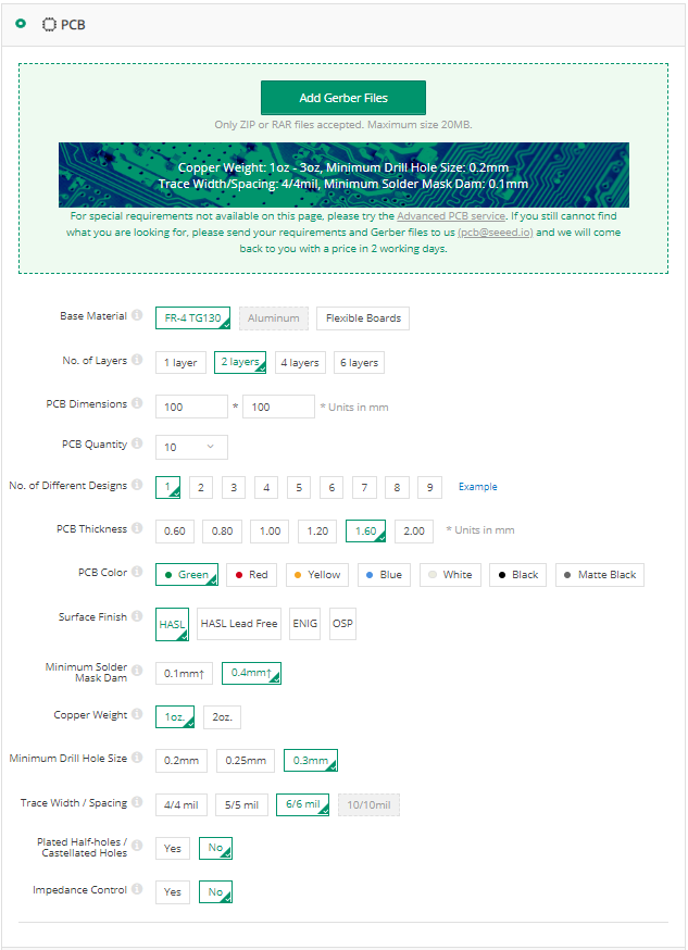
Choosing a PCB Manufacturer
I’m afraid I have very little experience to offer, but I can make the following observations.
For this level of project, I’ve found cheap, overseas PCB fabrication more than adequate. I’ve purchased other peoples designs from PCBWay and have used Seeed Fusion and JLCPCB for my own projects and have been very pleased with the results of all three.
Here are the links to the respective services:
- Seeed Fusion – this is who I used for many of my earlier boards.
- PCBWay – used when I ordered my Clumsy MIDI and support a lot of other makers.
- JLCPCB – often mentioned by (and support) other makers. I’ve used them most recently as they are often the cheapest option for small numbers of smaller boards.
Disclaimer: Seeed have sent me discount vouchers in the past that I’ve used for many of my early boards. I’m very happy to recommend you take a look and have been very happy with their service. But I tend to find the postage costs and costs of larger boards are higher than other options.
All services also support PCB assembly too, but I’ve not used that so far.
Of course there are many others, and there will almost certainly be some more local to you. I know OSHPark is very popular and supportive of makers in the US for example and Eurocircuits in Europe (I’ve used neither personally).
Testing Your PCB Assembly
Here is a list of basic checks I strongly recommend are followed when a PCB is first assembled prior to switching on.
- Leave any chips or add-on modules unconnected.
- This relies on using sockets or leaving soldering these components on last (see the “fishing line trick” later for add-on modules that will be soldered on eventually).
- Visually check for obvious shorts and good solder joints all round the board.
- This will need a magnifying glass and isn’t definitive. But if you spot an obvious problem then it saves time fixing that first!
- Check for shorts between power and GND pins.
- Note that if you are checking resistance and using potentiometers then there will be a resistance equivalent to the combined parallel resistances of your pots across the rails! So if you have 4 10KΩ pots connected in the typical “VCC-SIGNAL-GND” manner, then you’d expect to see 2K5Ω between VCC and GND (assuming no other links in the circuit).
- If there are several power sources (e.g. 5V and 3V3) then check there are no shorts there too.
- Check for continuity between all power points.
- Find the VCC pins on any IC sockets and check they connect to the correct power lines (e.g. 5V to 5V, 3V3 to 3V3, etc).
- Repeat for the GND pins. Sometimes areas of GND might not be linked when there are no external connections – many microcontrollers have several GND pins so sometimes GND areas might be connected to different pins.
- Do the same for any plug-in modules (e.g. displays, sound modules, etc).
- It might be worth powering up the board at this point with no additional connections and checking any basic operations and power readings around the board.
- Power off again and connect ICs and external modules.
- I often use the “fishing wire trick” to be able to plug in any additional modules (e.g. displays, sound modules, etc) without soldering. Nylon fishing wire in the holes gives enough traction to be able to push a header pin in, have it grip and make contact, without soldering. This allows for testing and debugging without committing your module to solder!
- Do anything else you can think of before connecting to your microcontroller or (possibly hard to replace these days) single board computer!
The Fishing Line Trick
This is a simple trick I first saw mentioned on Twitter. Threading nylon fishing line wire though pin header holes gives enough traction to be able to push a header pin in, have it grip and make contact, without soldering.
This is massively useful for testing as it allows you to check everything is working, including any add-on modules or pin header connections, whilst still giving options for debugging and without having to solder them down straight away!
Once everything is ok, the header pins can be pulled out again, the nylon wire removed, and then the pins can be properly soldered in place.
Simple DIY Electronic Music PCB Projects
Here is a selection of my projects so far. They are listed under the following headings:
- For Raspberry Pi
- For Raspberry Pi Pico
- For Arduino Uno
- For other Arduino (Nano, Pro Mini, Pro Micro, etc)
- For Seeed XIAO
- For ESP32
- For Analog, Modular or EuroRack
- Other
For Raspberry Pi

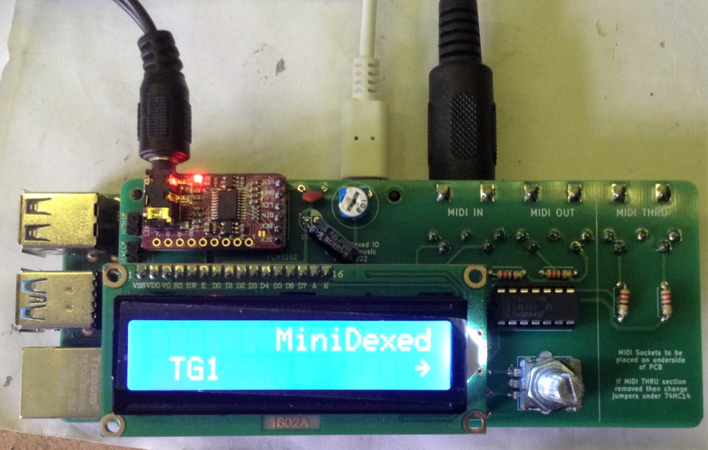

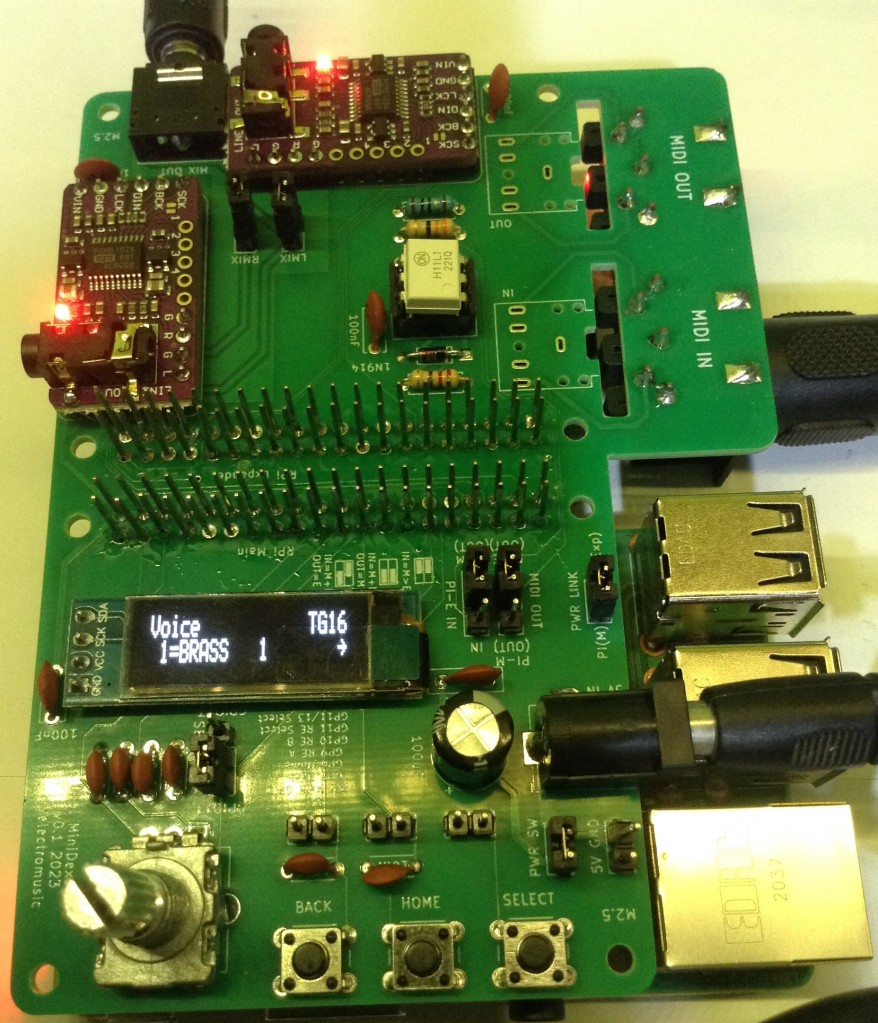
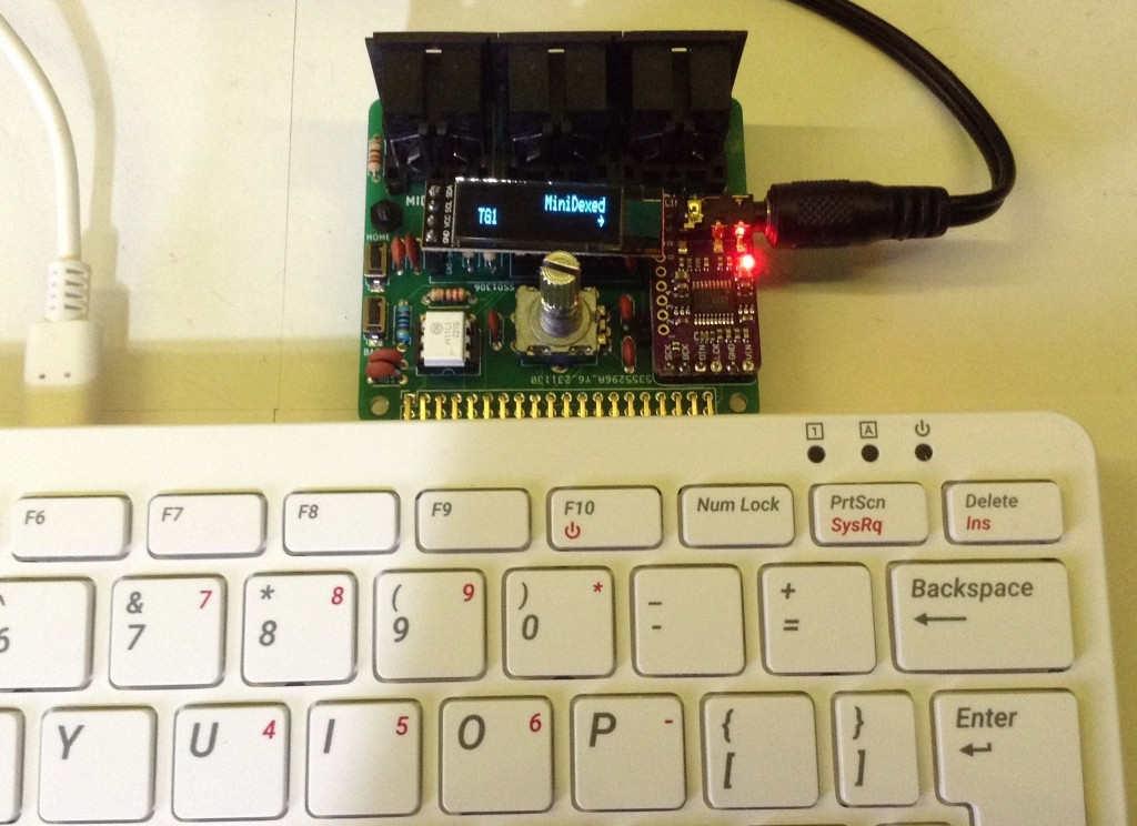
- MiniDexed IO Board – Design and Build: SSD1306 Version, HD44780 Version – V2 Design and V2 Build
- Two designs for a Raspberry Pi add-on IO module with a display, rotary encoder and MIDI to support MiniDexed. Note there is a V2 of the SSD1306 version.
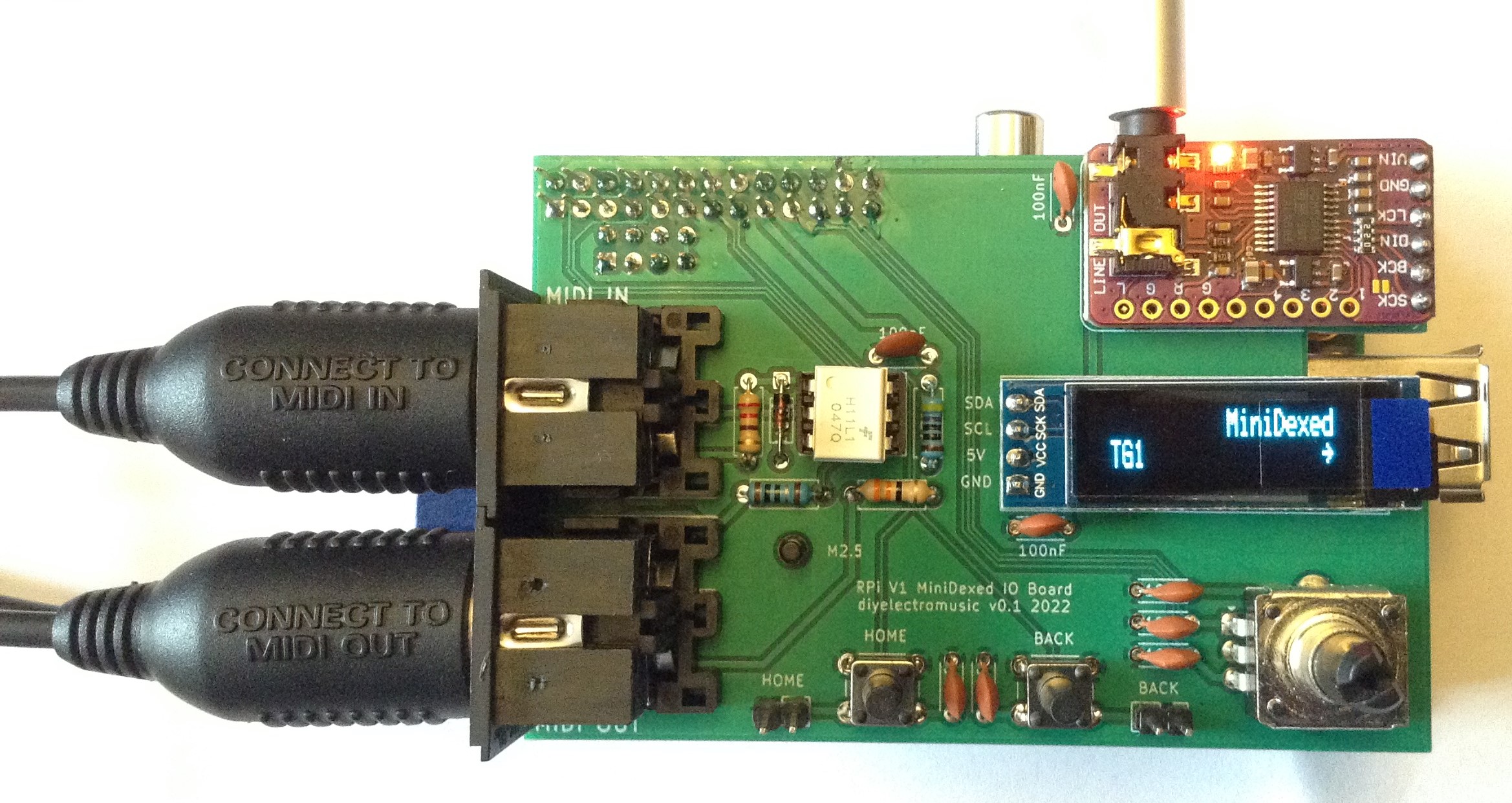
- MiniDexed IO Board for RPi V1 – Design and Build
- A Raspberry Pi add-on IO module with display, rotary encoder and MIDI to support MiniDexed on a Raspberry Pi V1.
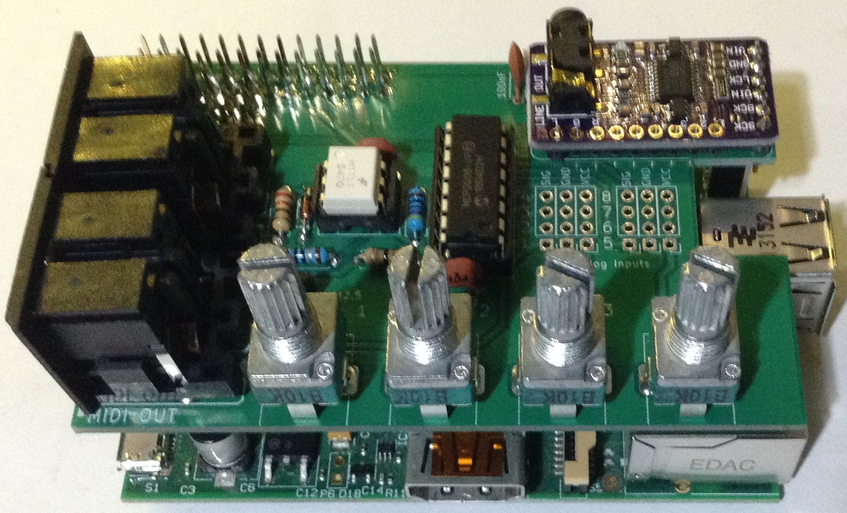
- RPi V1 Synth IO Board – Design and Build
- An IO board for a Raspberry Pi V1 (with a 26-way GPIO header and an 8-way P5 header) supporting MIDI, potentiometers and a DAC.
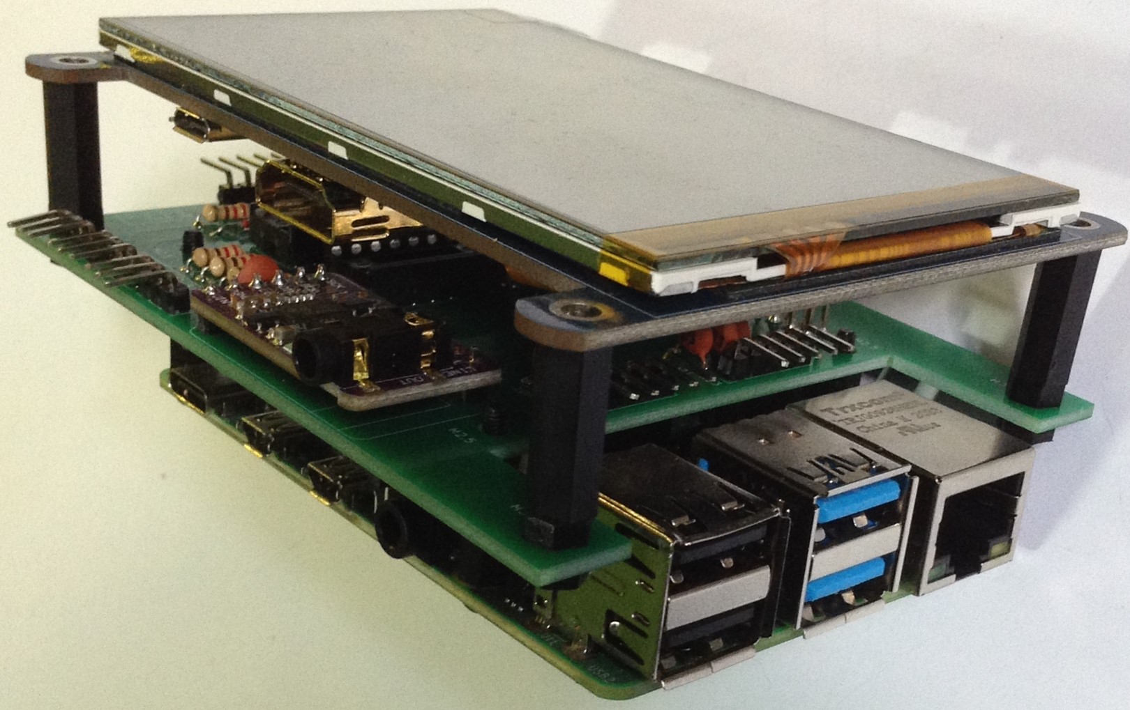
- Zynthian IO Board – Design and Build
- An IO board for a Raspberry Pi V3 or V4 and a Waveshare touchscreen, proving MIDI, DAC, and rotary encoders to build a Zynthian synth.
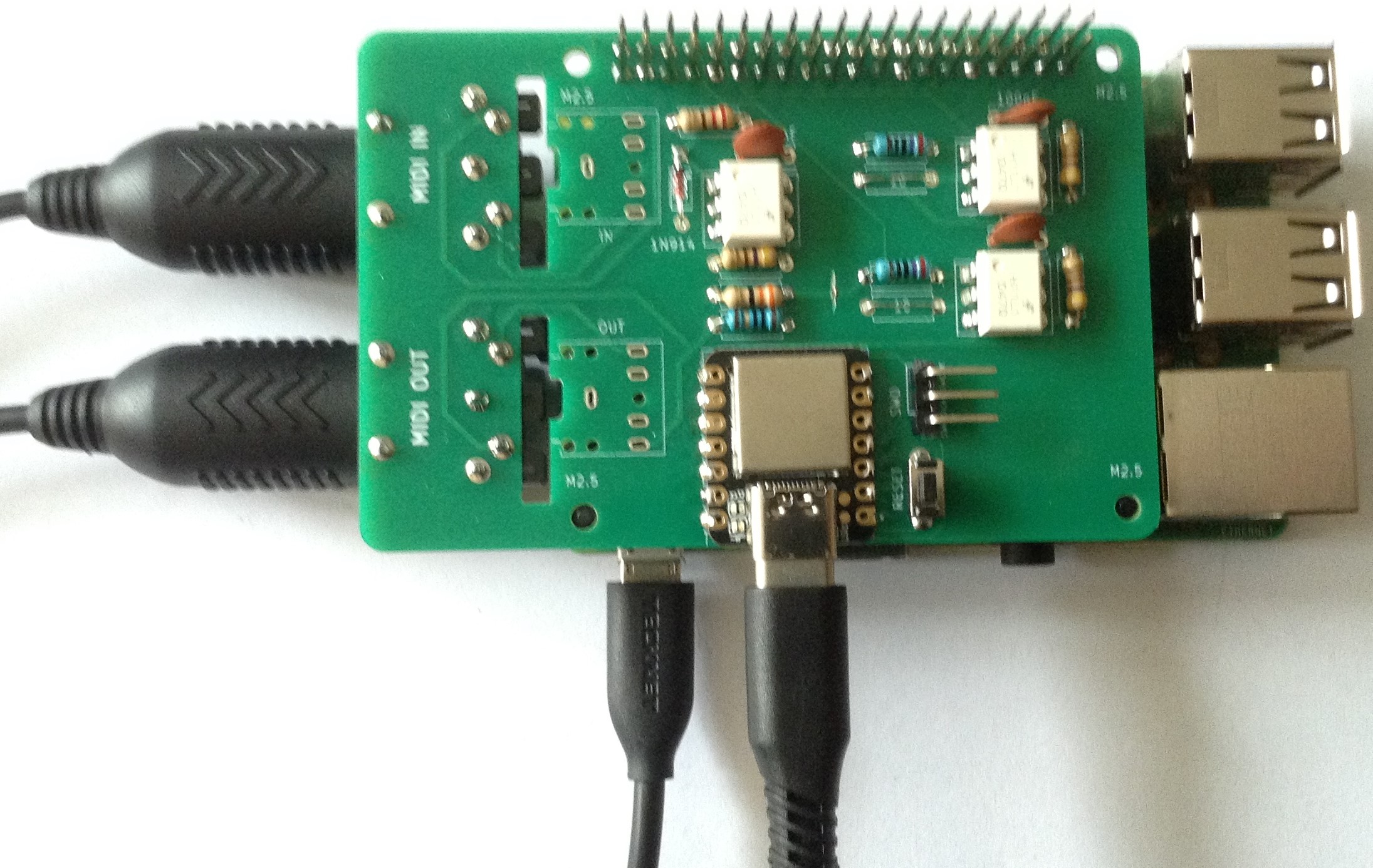
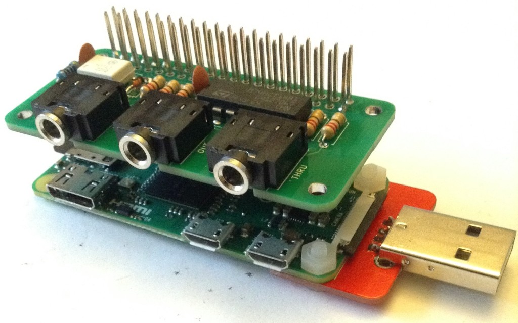
- XIAO Pi USB MIDI Device – Design and Build
- An add-on board for a Raspberry Pi that provides a USB MIDI Device link using a Seeed Studio XIAO SAMD21.
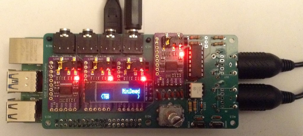
- Dual MiniDexed IO Board – Design and Build
- An add-on board that allows two Raspberry Pis, both running MiniDexed, to be linked into a dual unit.
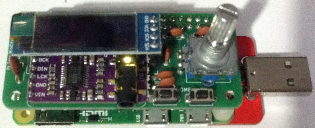
- Pi Zero MiniDexed IO Board – Design and Build
- An add-on board to provide display, encoder, buttons and optional DAC for a Raspberry Pi Zero.
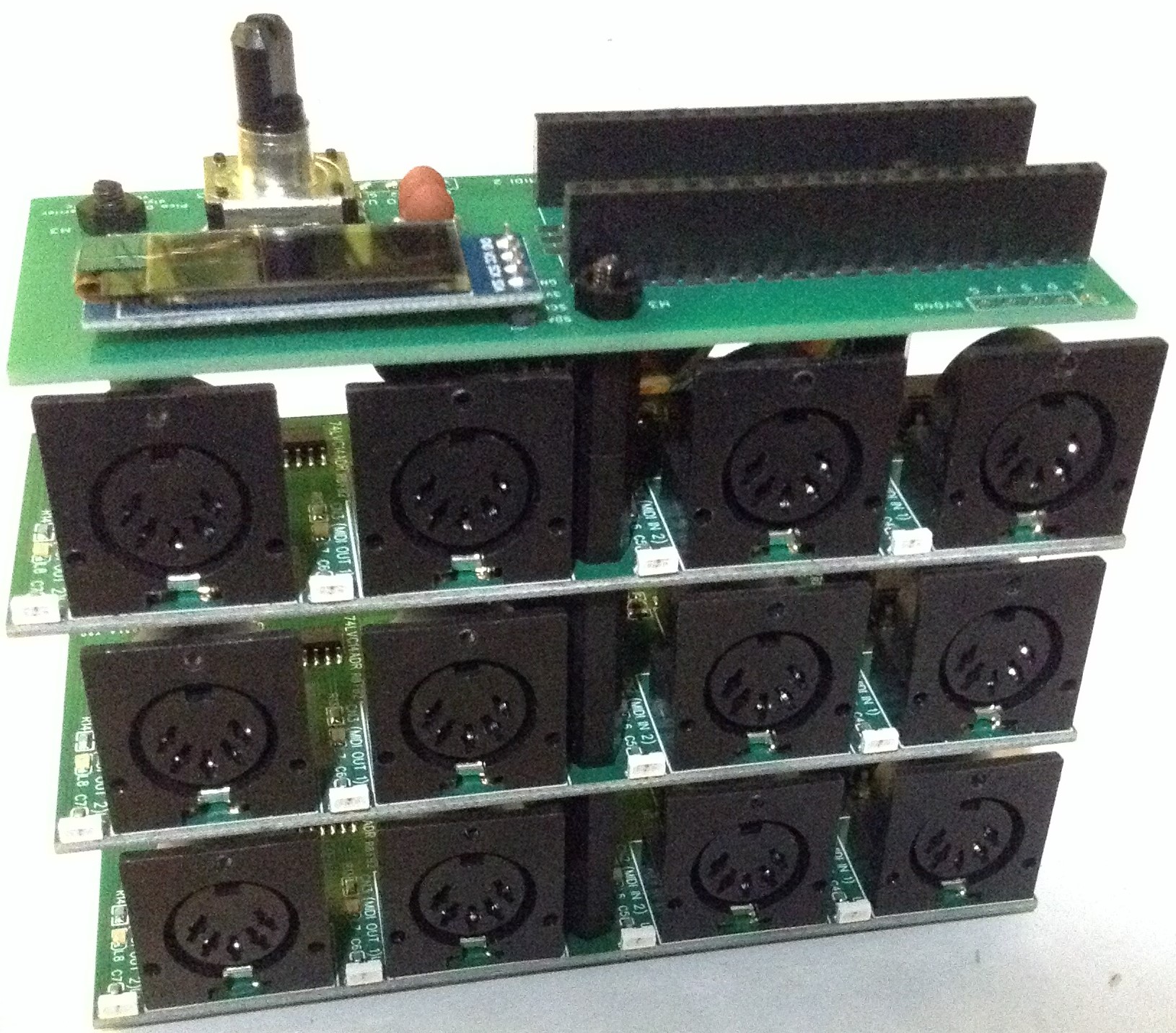
- Pi Zero MIDI Interface – Design and Build
- A stackable MIDI interface for a Pi Zero with MIDI IN, OUT, THRU TRS sockets.
- Pi 400 MIDI and Audio Module – Design and Build
- This is a MIDI and I2S DAC audio board with optional MiniDexed IO controls for a Raspberry Pi 400.
- RPi 5 Quad DAC MiniDexed IO Board – Design and Build
- This is an IO board for a Raspberry Pi 5 supporting four GY-PCM5102 DACs for use with MiniDexed.

- RPi Zero EuroRack MiniDexed – Design and Build and MT32-Pi.
- A prototype MiniDexed in 8HP EuroRack format.
For Raspberry Pi Pico
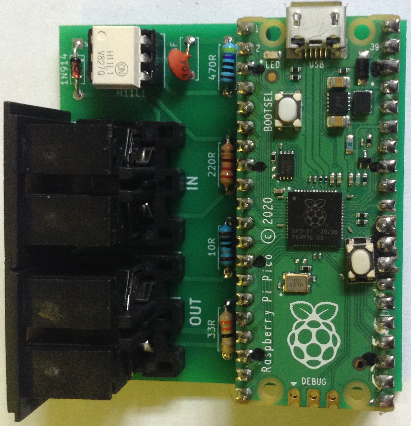
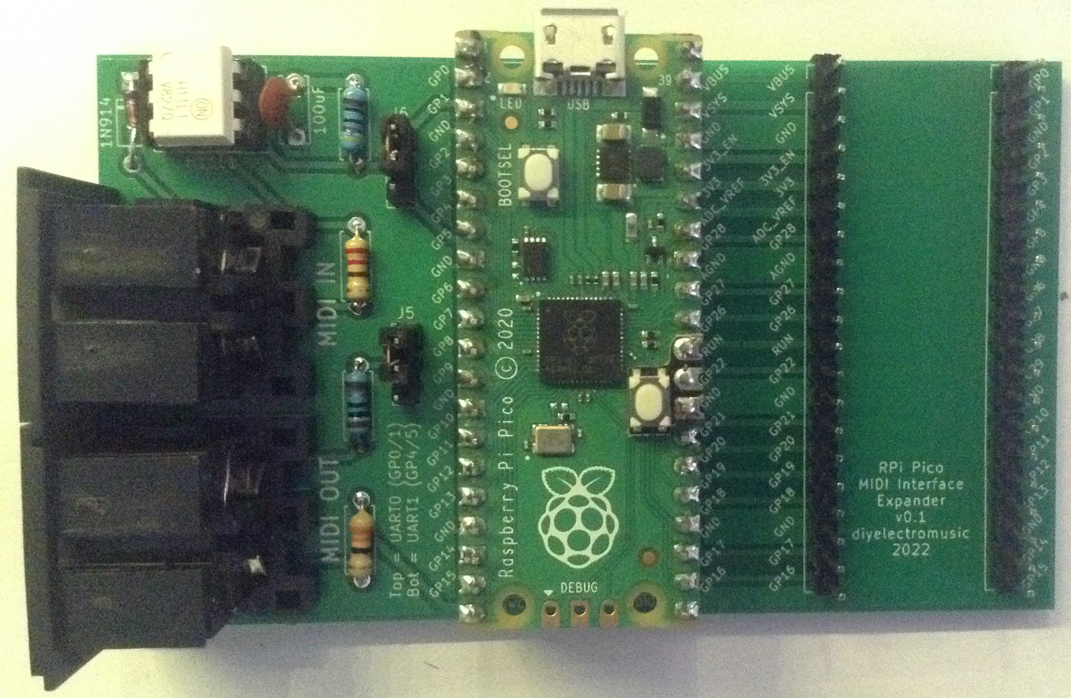
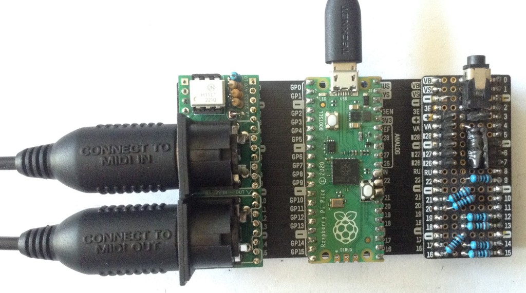
- MIDI Interface – Design and Build
- A Raspberry Pi Pico MIDI interface that allows you to plug the Pico into the PCB.
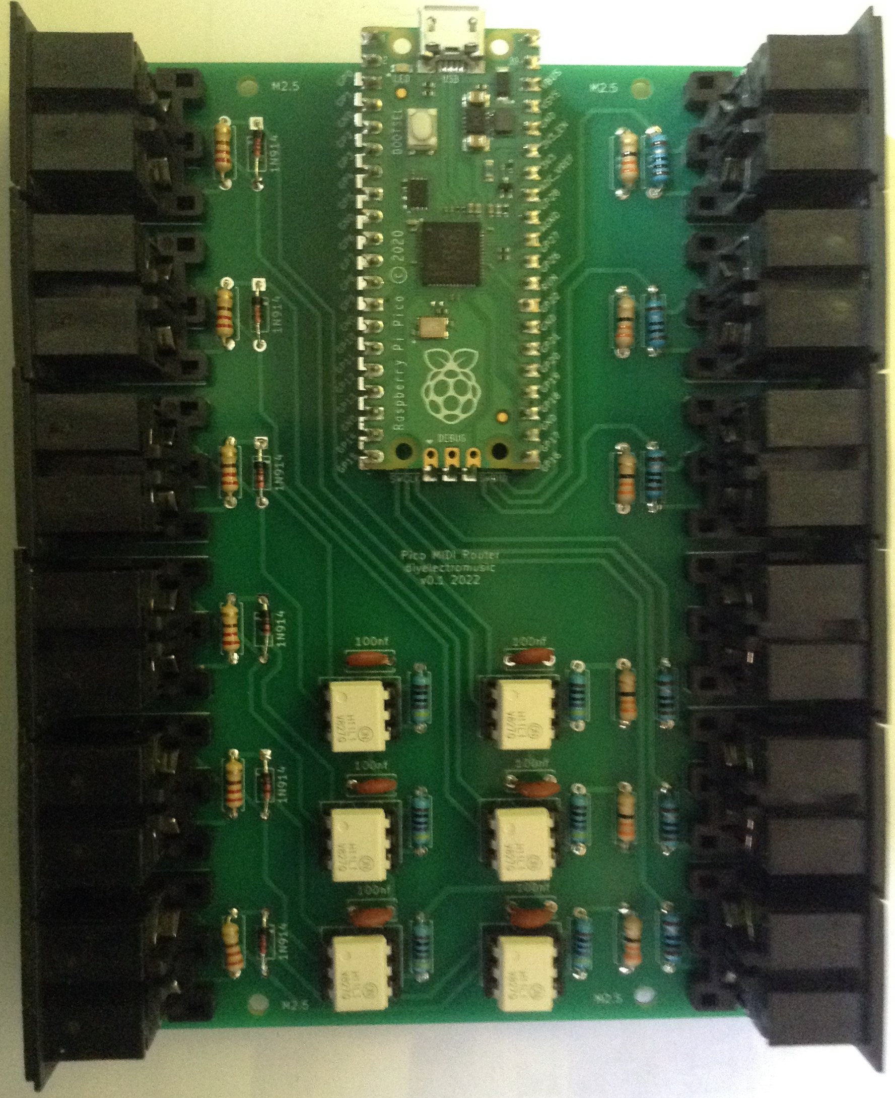
- Multi MIDI Router – Design and Build
- The design for a custom PCB for my Pico Multi MIDI Router.
- MIDI Proto Expansion – Design and Build
- A Raspberry Pi Pico MIDI interface with an additional expansion area for additional modules.
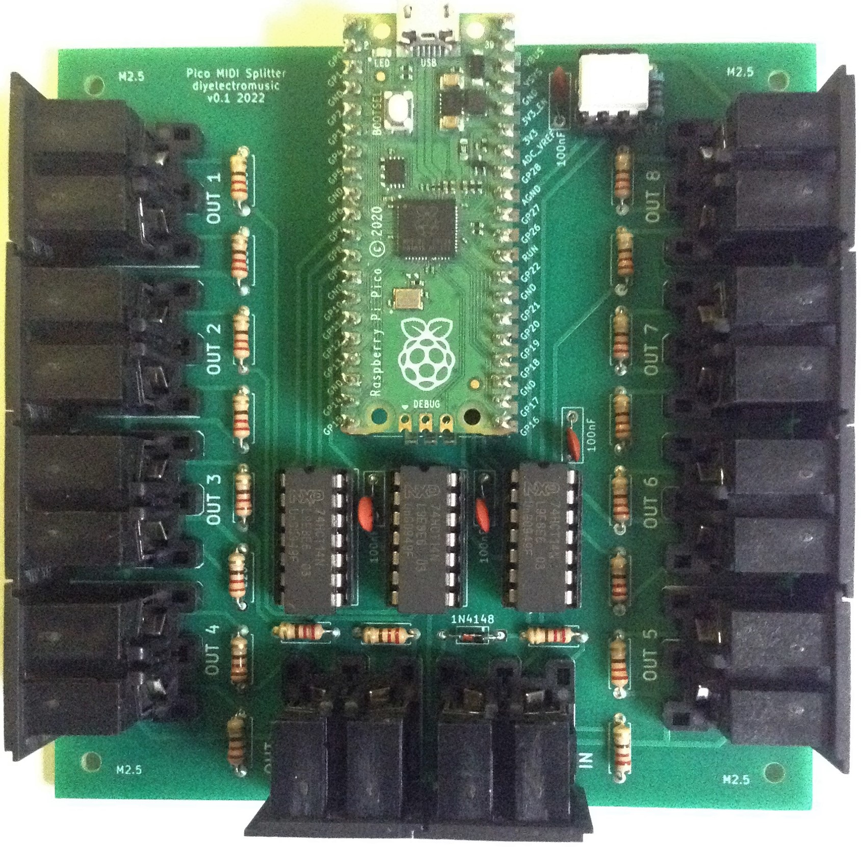
- MIDI Splitter – Design and Build
- This design allows for a single MIDI IN to be split out using a Raspberry Pi Pico to up to 8 (optionally 9) MIDI OUT ports.
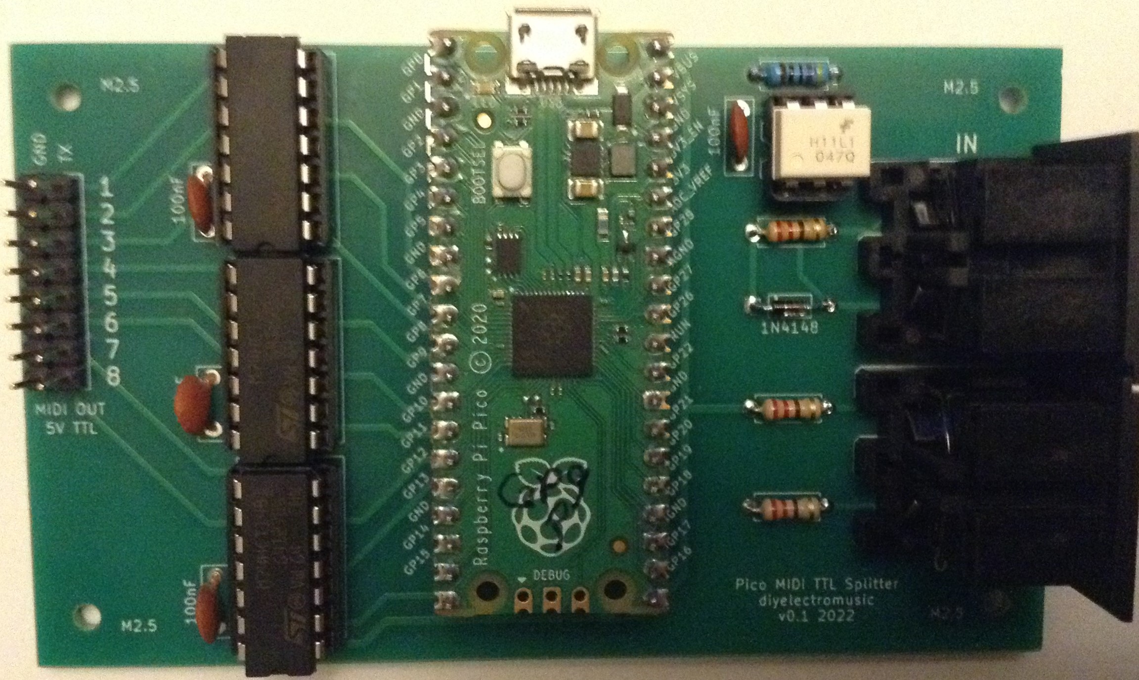
- TTL MIDI Splitter – Design and Build
- A slightly cut-down version of the above that provides eight TTL (5V) serial line outputs rather than “true MIDI” from a single MIDI IN port.
- Pico MIDI “Pack” – Design and Build
- A “pack” style MIDI interface within the board footprint of a Pico.

- Pico Touch MIDI Controller – Design and Build
- A Pico-based touch MIDI controller that can be used directly with my ESP32 Educational Synth Thing.

- Pico MIDI Touch Board – Design and Build
- A Pico-based touch MIDI controller with crocodile clip-friendly and Lego-compatible holes.
For Arduino Uno
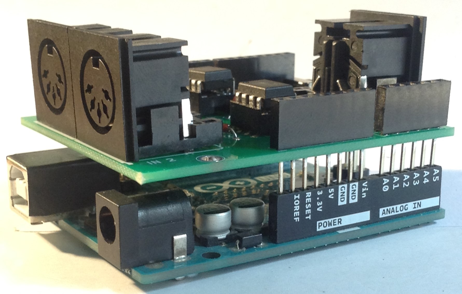
- Dual MIDI Merge Shield – Design and Build
- A 2xMIDI IN, 1xMIDI OUT shield for MIDI merge functions on an Arduino Uno.
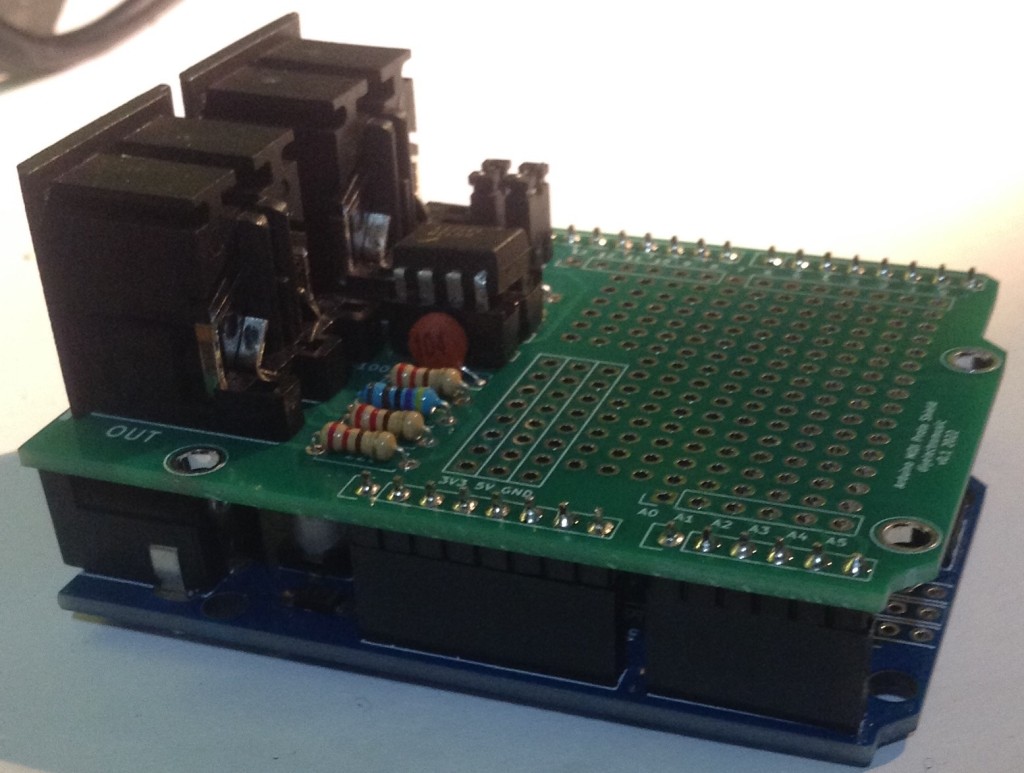
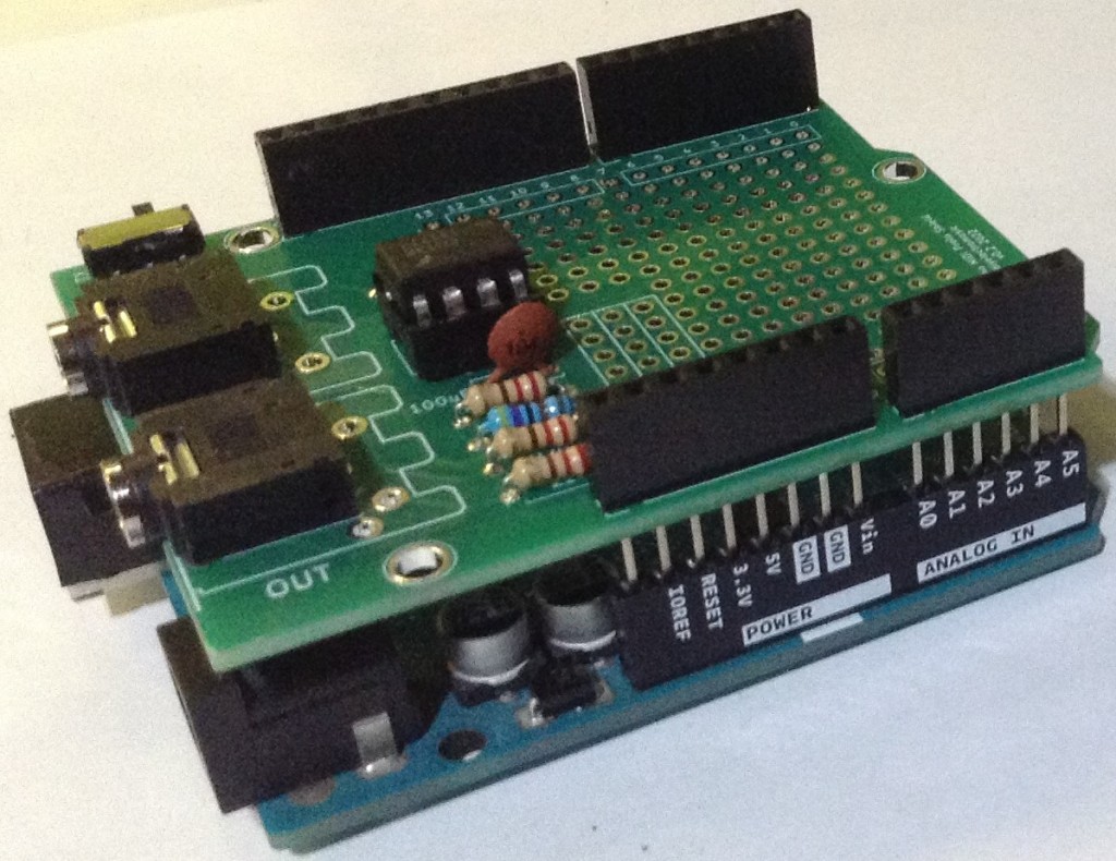
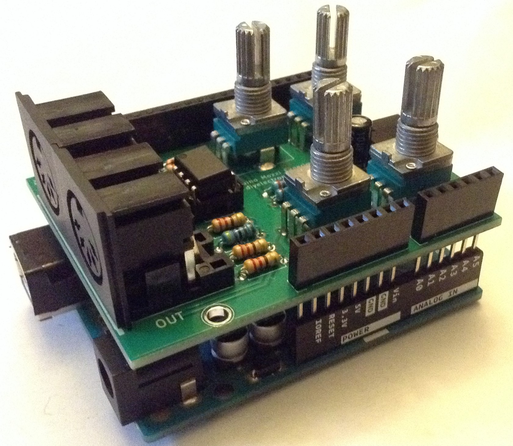
- MIDI Proto Shield – Design and Build
- Here is a design for an Arduino shield with a MIDI IN/OUT interface and a built-in prototyping area. There are three versions: MIDI DIN only; MIDI DIN or TRS; MIDI DIN or TRS with additional IO breakouts.
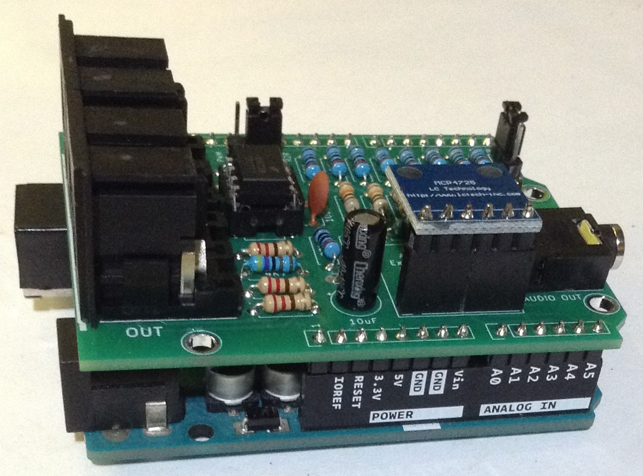
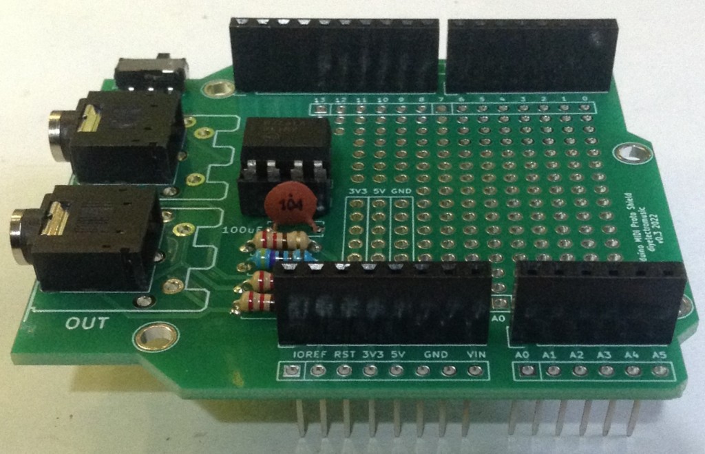
- Audio Experimenter Shield – Design and Build
- A shield with three different digital to analog, audio output methods: PWM, R2R and MCP4725 DAC.
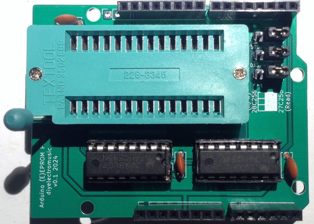
- Arudino EEPROM Reader/Programmer – Design and Build
- A shield designed for reading 27Cxxx EPROM devices.

- Arduino Clock Generator Shield – Design and Build
- A shield designed to output up to 6 5V GATE signals for an analog synthesizer.

- Arduino Drum Trigger to MIDI Shield – Design and Build
- A shield with up to 6 5V trigger inputs and a MIDI output.

- Arduino Atari 2600 Controller Shield – Design and Build – Revisited
- A simple breakout board for Atari 2600 style controllers and an Arduino Uno.

- Arduino SP0256A-AL2 Shield – Design and Build
- Uno shield format board for the SP0256A-AL2 vintage speech synth chip.

- Arduino AY-3-8910 Shield – Design and Build
- Uno shield format board for the AY-3-8910 vintage sound chip.
For other Arduino (Nano, Micro, Pro Mini)
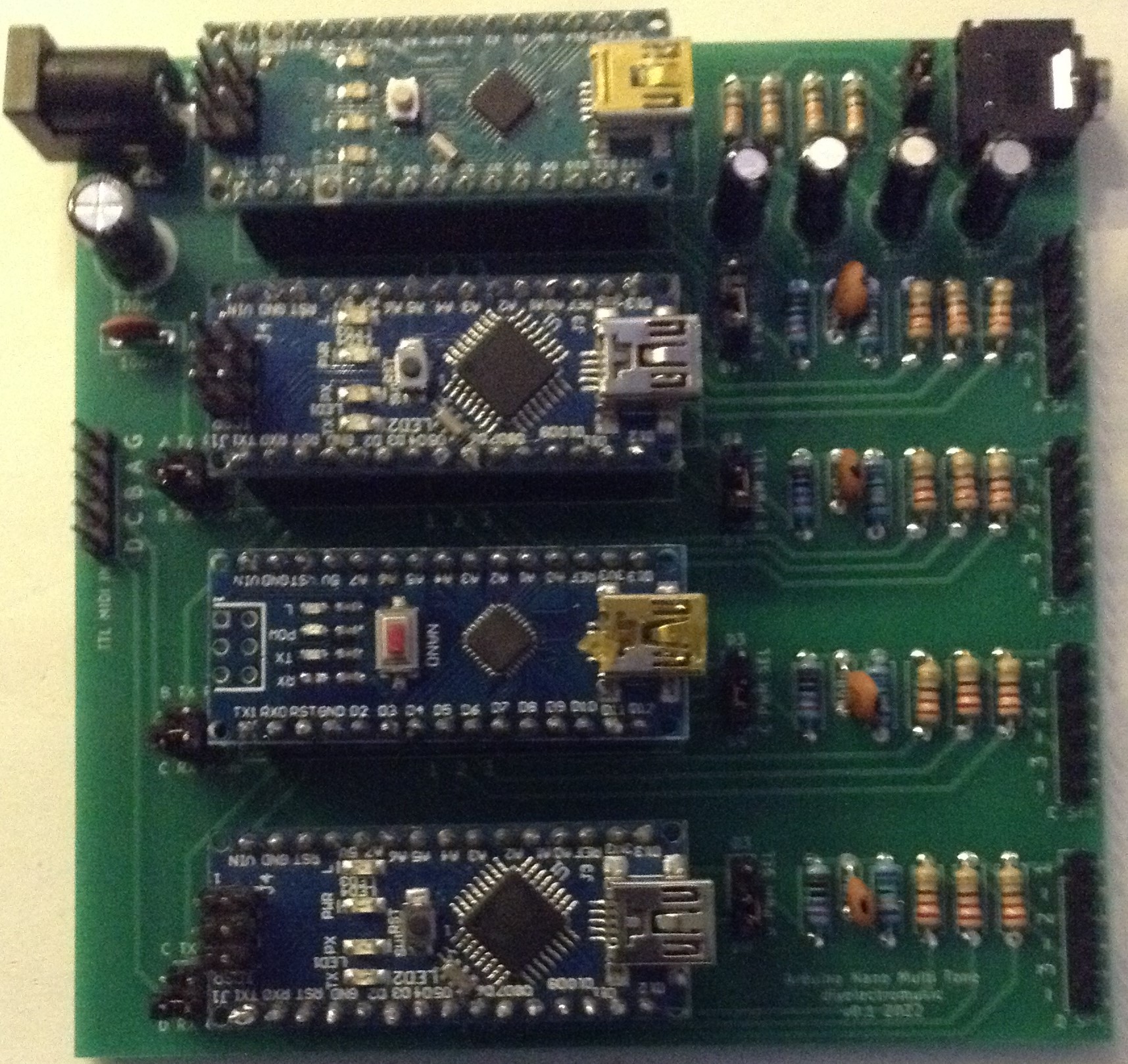
- Multi-tone or PWM Board – Design and Build
- A carrier board for four Arduino Nanos for use with tone() or PWM outputs.
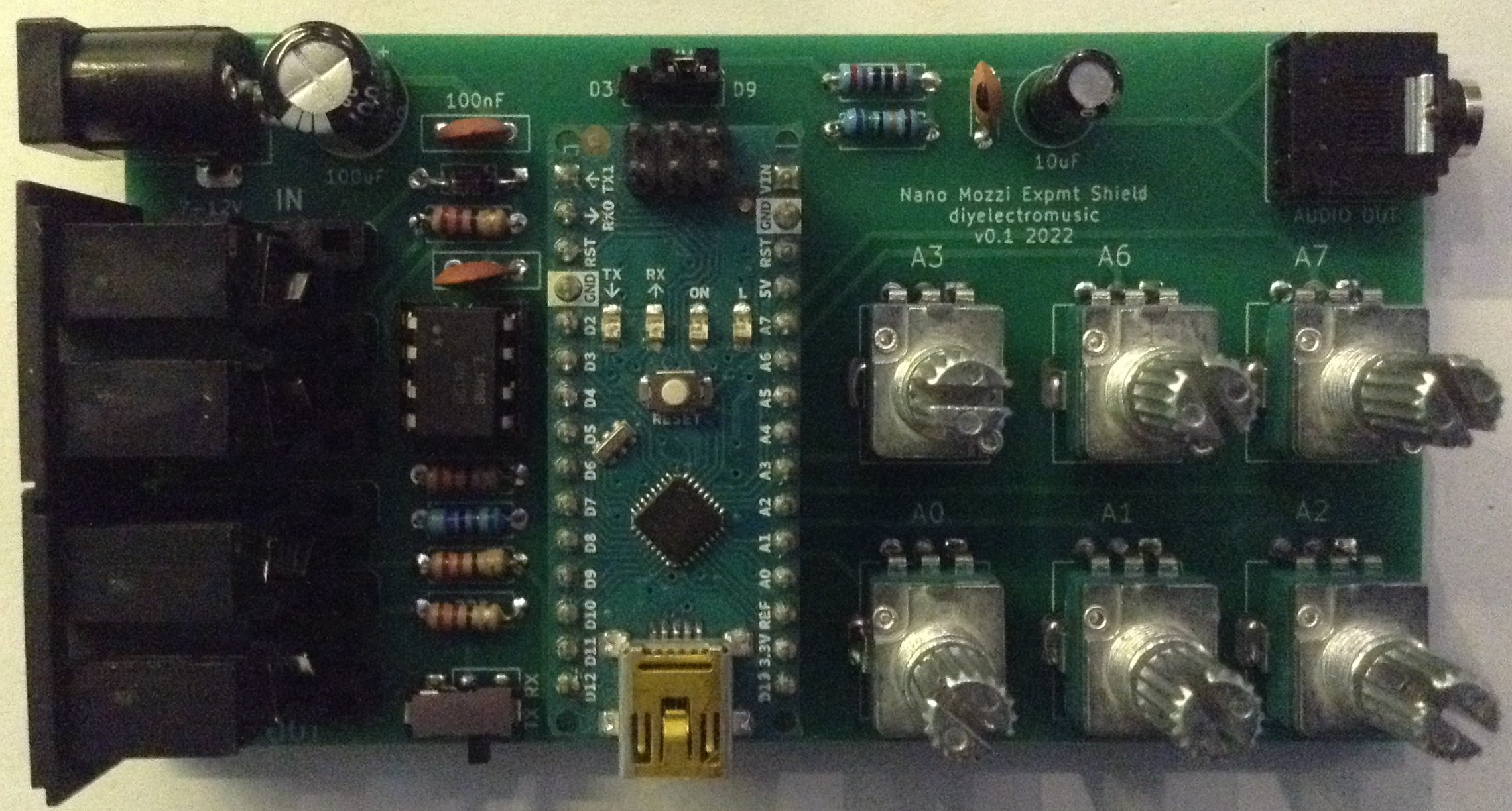
- Mozzi Experimenter Shield for the Nano – Design and Build.
- A carrier board designed for Mozzi and audio PWM experiments.
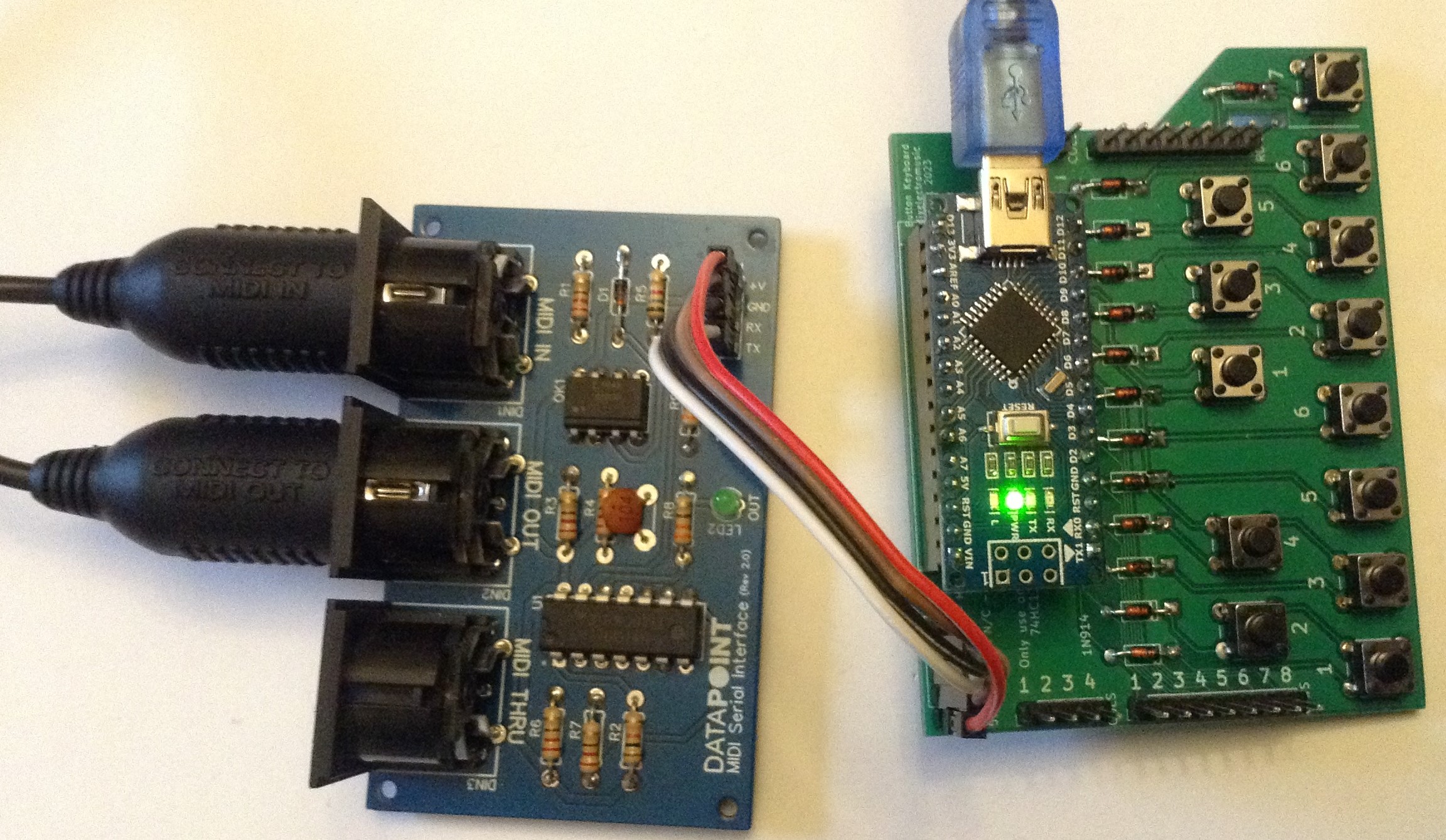
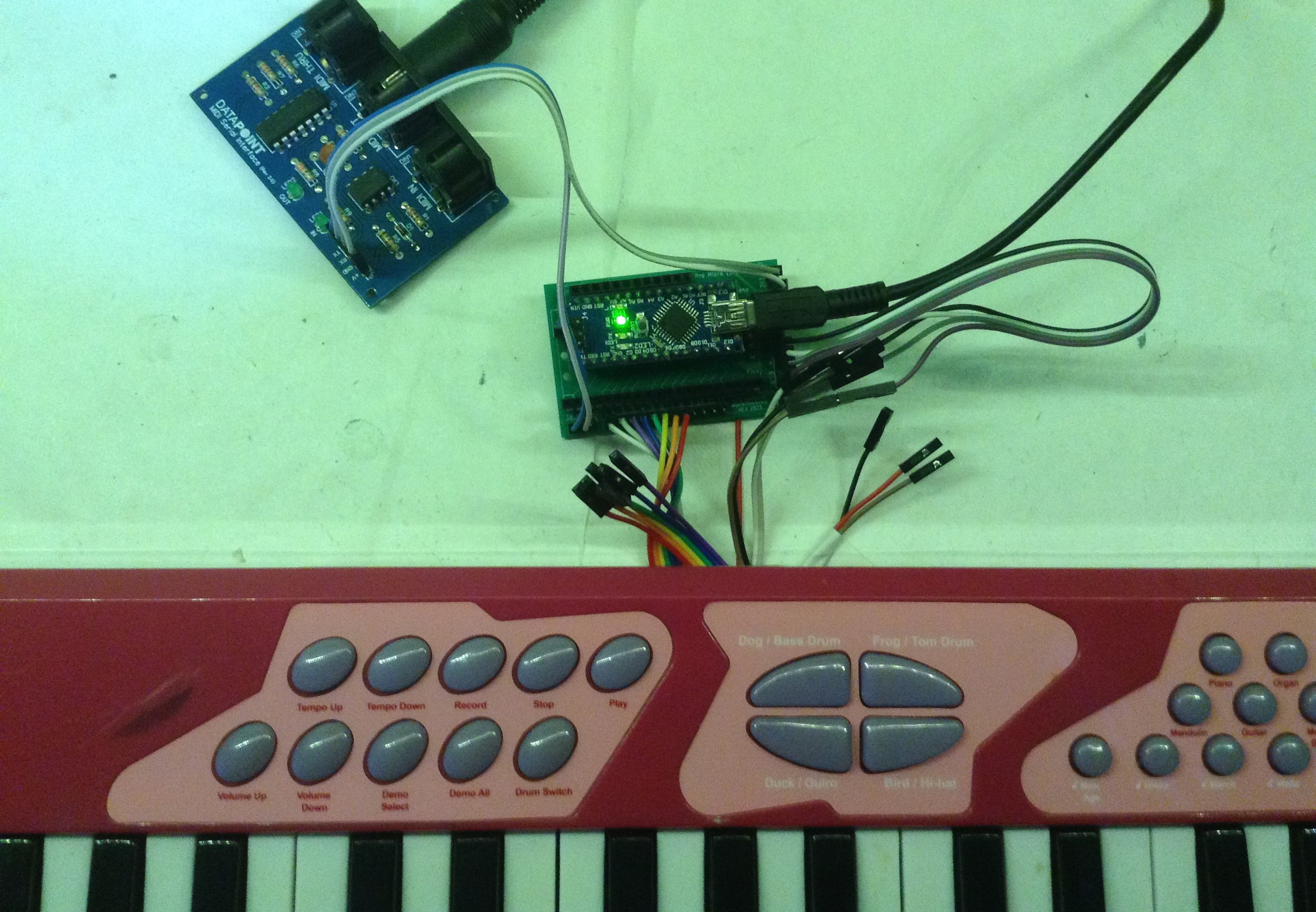
- Tactile Button Keyboard – Design and Build
- A tactile button expandable music keyboard supporting three modes: direct connection, on-board Arduino Nano, or 74HC138.
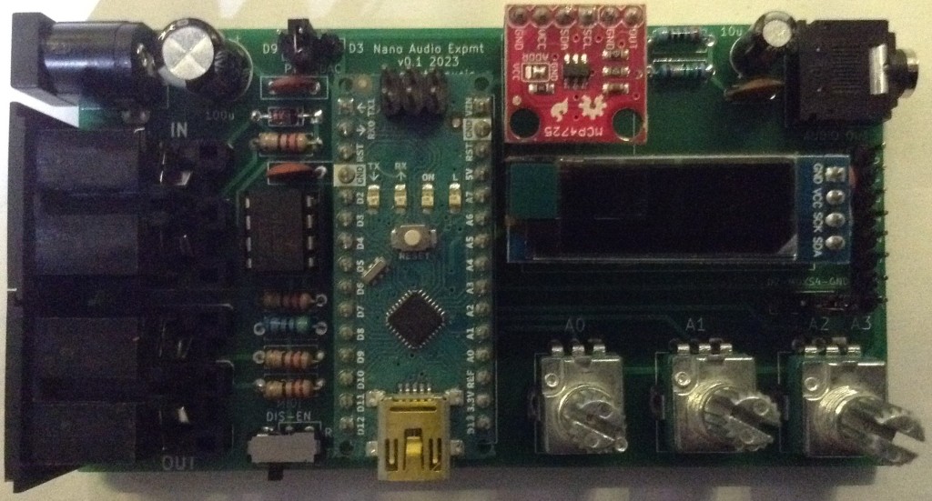
- Audio Experimenter Shield – Design and Build
- An experimenter board for the Arduino Nano with MIDI, SSD1306 display, MCP4725 DAC, pots and audio output filter.

- Arduino Pro Mini USB Host – Design and Build
- A USB host to MIDI converter that can use an Arduino Pro Mini or an Adafruit Trinket M0.

- Arduino Nano MIDI Proto Shield – Design – Build
- Prototyping board with built-in MIDI interface for the Arduino Nano.

- Arduino Pro Mini USB Host Proto Shield – Design – Build
- Prototyping board with build-in USB Host shield and power for a Arduino Pro Mini.

- Arduino Pro Mini USB MIDI Host with CV Output – Design – Build
- USB MIDI to Serial MIDI or CV/GATE converter based on an Arduino Pro Mini and USB Host shield.

- Arduino Quad AY-3-8910 Experimenter Board – Design – Build
- Driving up to four AY-3-8910 vintage chips from an Arduino Nano.
For Seeed Studio XIAO
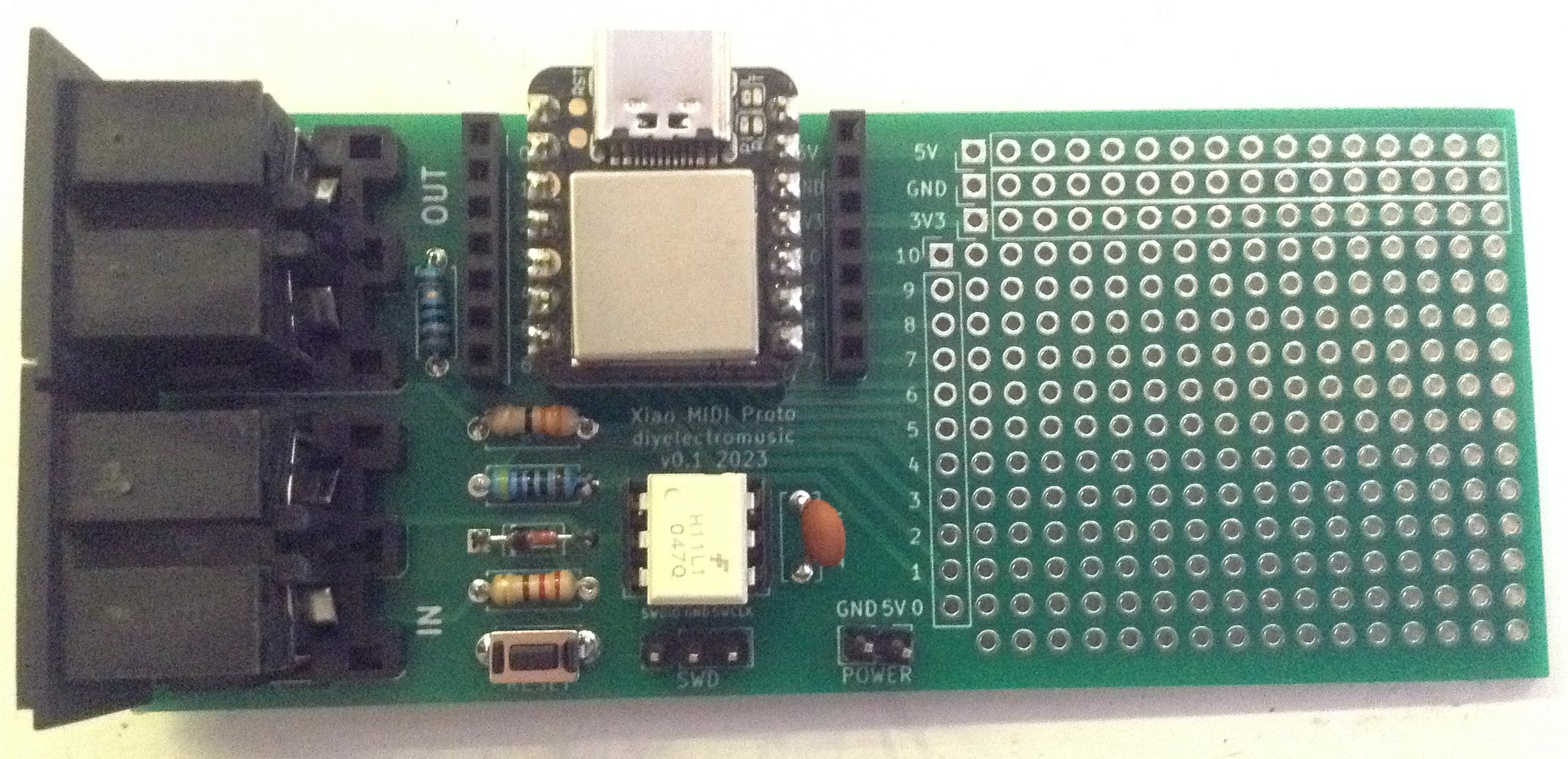
- MIDI Proto Interface – Design and Build
- A MIDI interface with prototyping area for the Seeed Studio XIAO format boards.
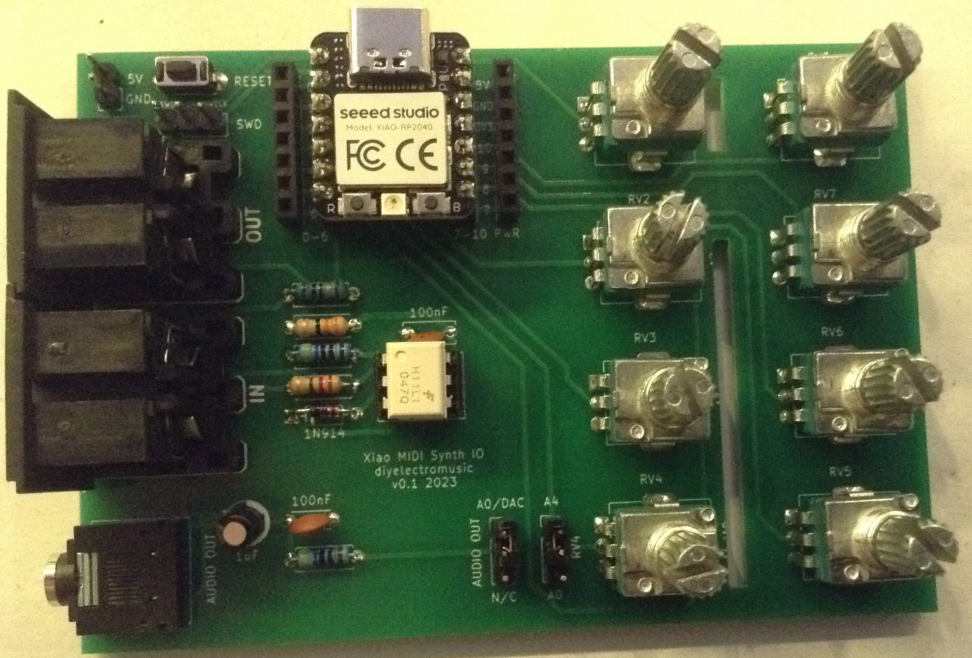
- MIDI Synth Board – Design and Build
- A MIDI and potentiometer IO board for the Seeed Studio XIAO format boards.
For ESP32
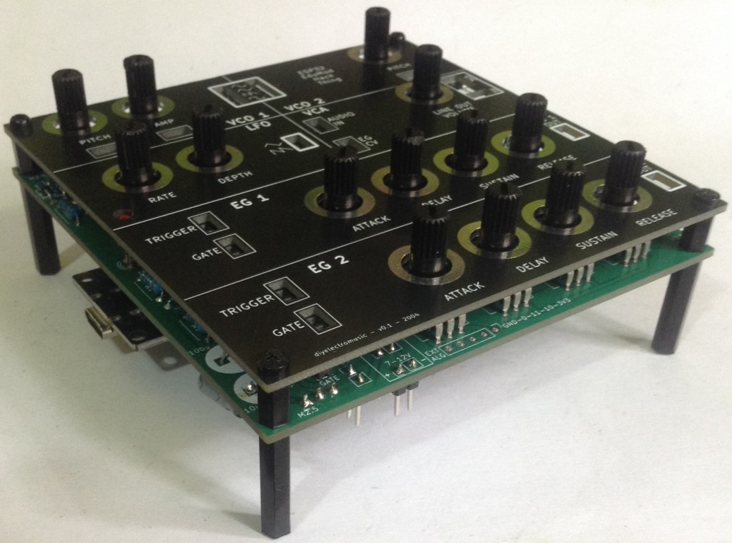
- Educational Modular Synth Thing – Design and Build
- Design, development, and build for a pseudo analog synth experimental platform for possible educational purposes.

- ESP32 Mozzi Experimenter PCB – Design and Build
- Prototyping and experimenting board with MIDI, DAC output and 8 potentiometers.

- Waveshare Zero MIDI Proto PCB – Design and Build
- A MIDI prototyping board designed for use with Waveshare Zero format microcontrollers (ESP32, RP2040, etc).

- ESP32-S3 DevKit Experimenter PCB – Design and Build
- MIDI, PWM, potentiometer prototyping board for a ESP32-S3 DevKitC module.

- Waveshare Zero Multi-SPI Display PCB – Design, Build, and Expander
- A carrier board for up to four SPI TFT displays and a Waveshare Zero format board.
Analog, Modular or EuroRack

- EuroRack test power supply module – Design
- My own design for a EuroRack power supply that I use for testing. Full design documented but not published.

- 6HP EuroRack MCU Experimenter Module – Design, Build and Usage Notes
- A prototyping board support either an Arduino Nano or Raspberry Pi Pico for use with DIY EuroRack systems.

- 6HP EuroRack MCU Pots and Jacks Module – Design and Build
- A breakout board for potentiometers and jacks for use with my 6HP EuroRack MCU Experimenter Module.

- 6HP DaisySeed MCU board for my MCU Experimenter Module – Design and Build
- A MCU board for my experimenter module using a Daisy Seed microcontroller.
Other
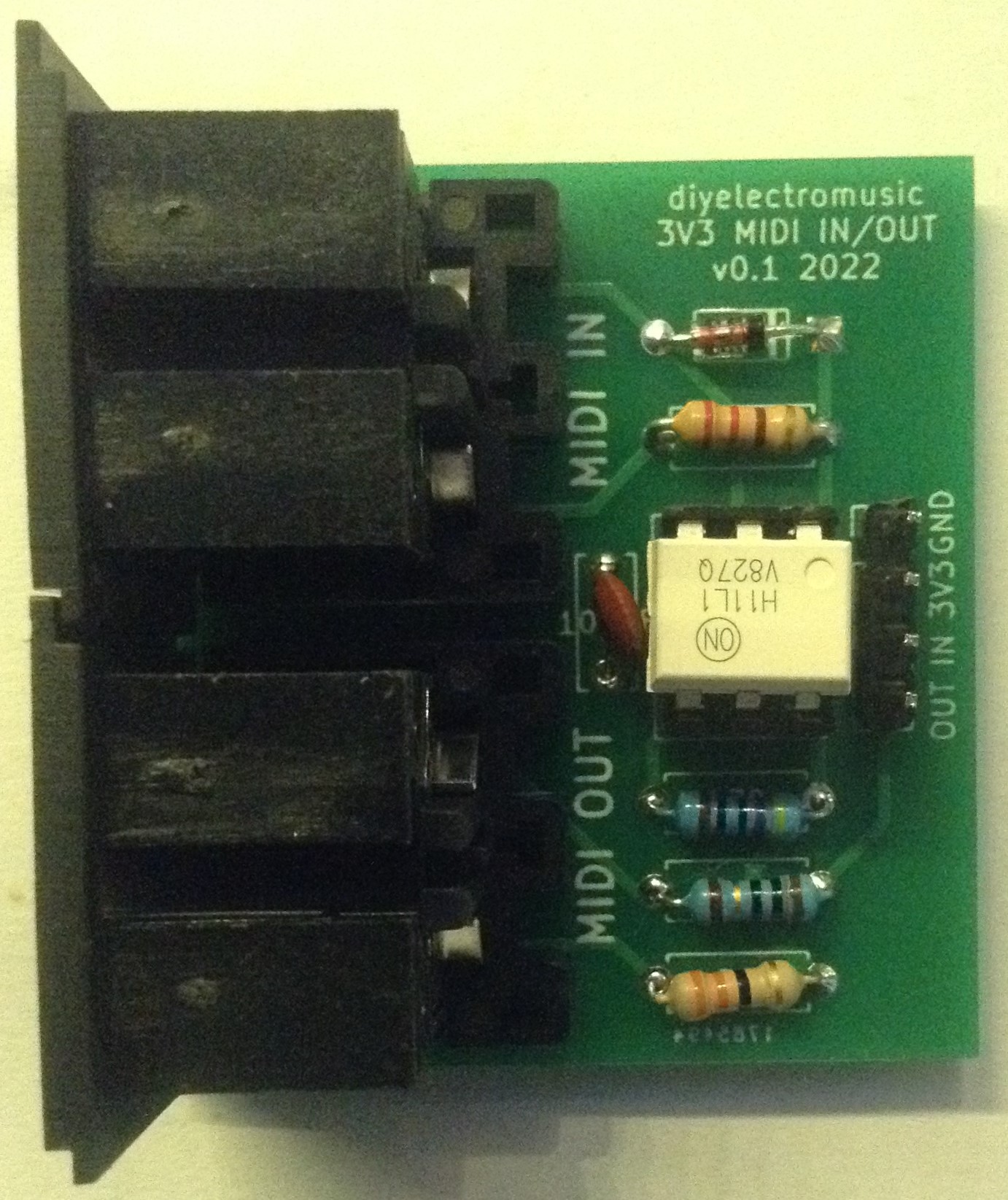
- Generic 3V3 MIDI Module – Design and Build
- The design for a custom PCB version of a generic 3V3 compatible MIDI IN and OUT circuits.
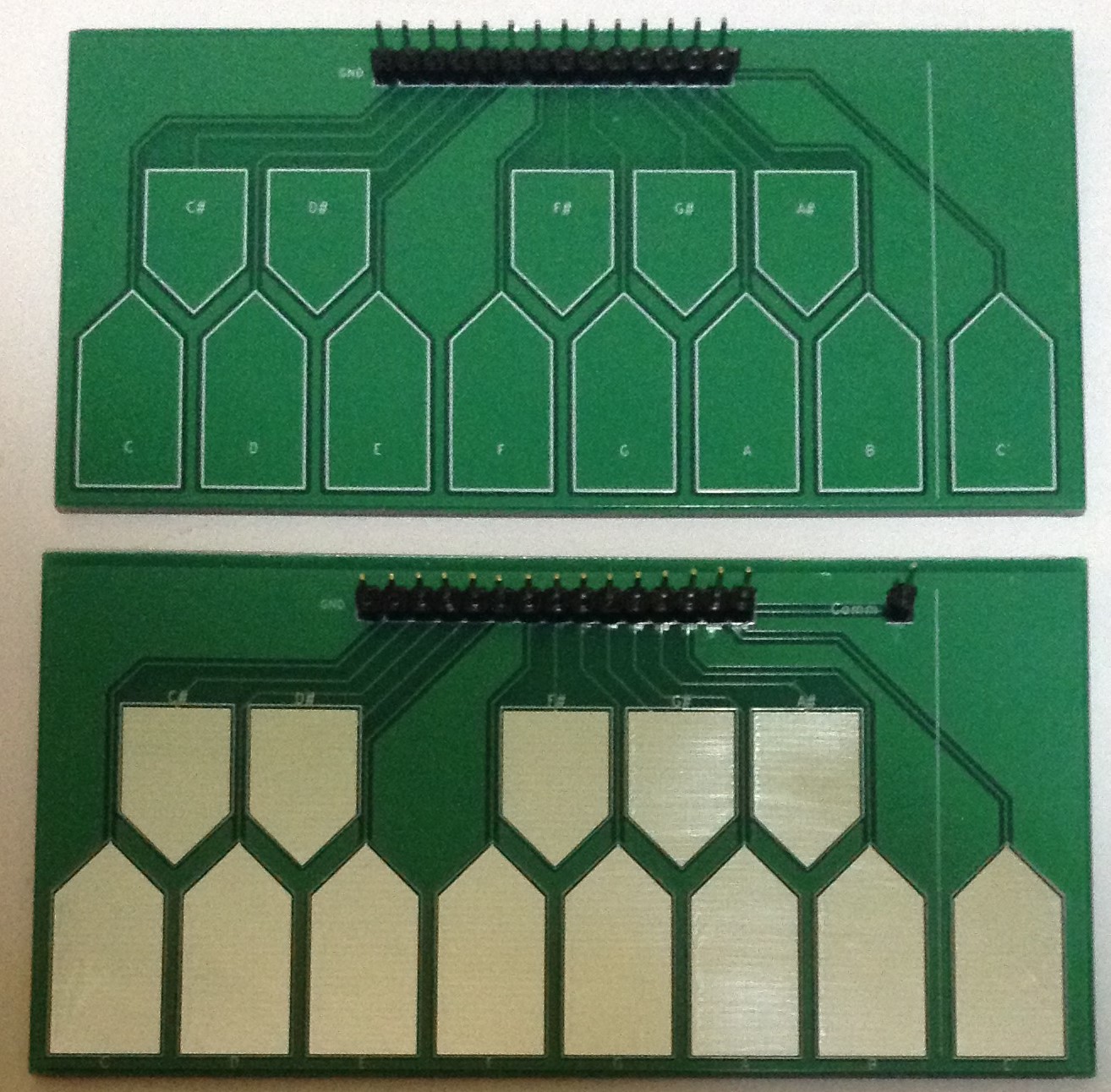
- Touchpad Keyboard – Design and Build
- A PCB touchpad music keyboard supporting two designs on one board: one designed for use as a capacitive touch keyboard, and one for use with a stylus.
- Pico, Nano, Micro Keyboard Matrix – Design and Build
- A PCB breakout board for GPIO for one of a Raspberry Pi Pico, Arduino Nano, or Sparkfun Pro Micro to support building keyboard matrices.
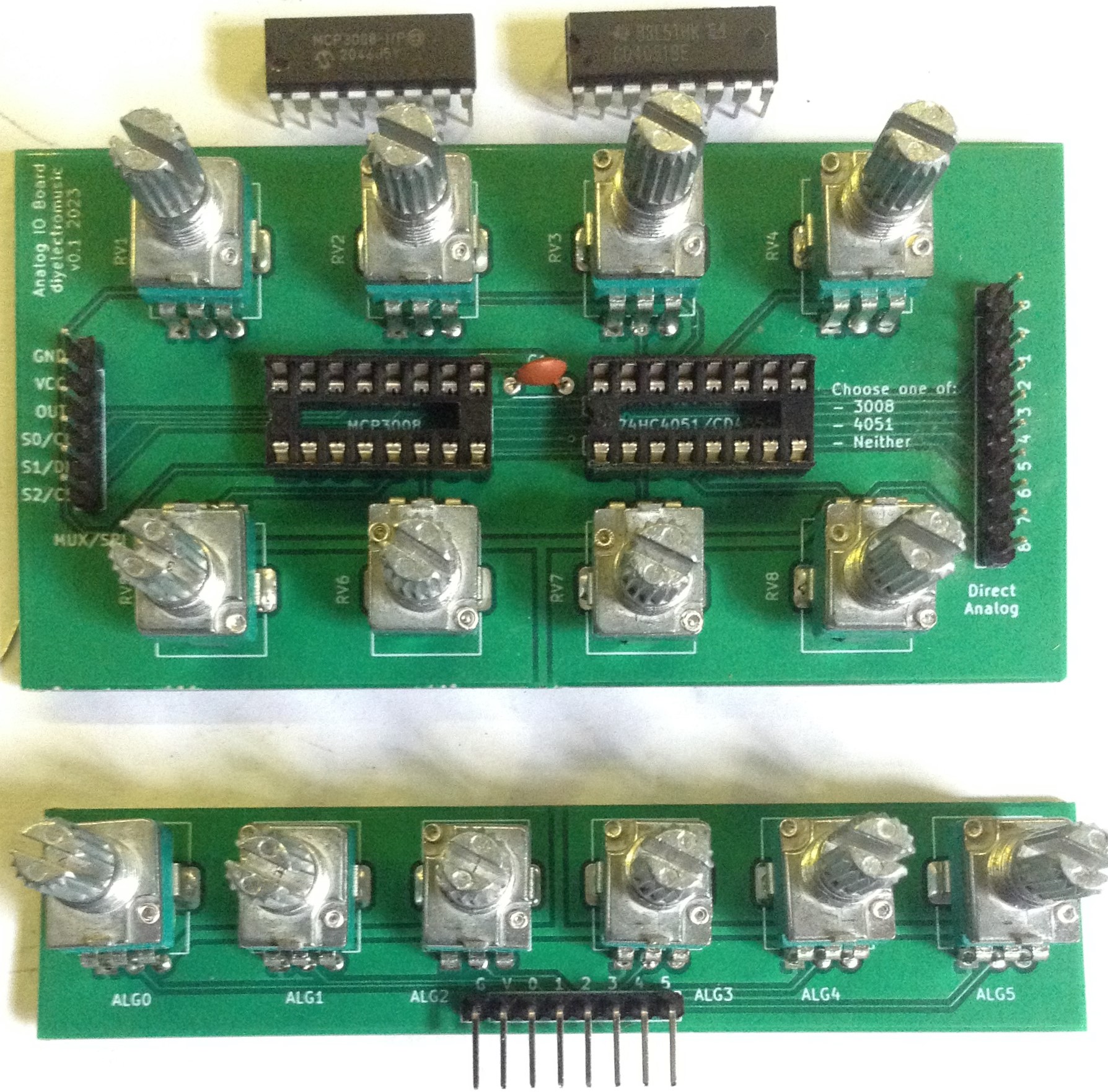
- Analog IO Board – Design and Build
- A breakout board for PCB mounted potentiometers which can be read directly, via a 4051 multiplexer or over SPI using an MCP3008.
- Raspberry Pi Pico Dual MIDI Module Carrier Board – Design and Build
- A bespoke circuit to support a Raspberry Pi Pico in use with a special dual-MIDI interface module that was designed for me.
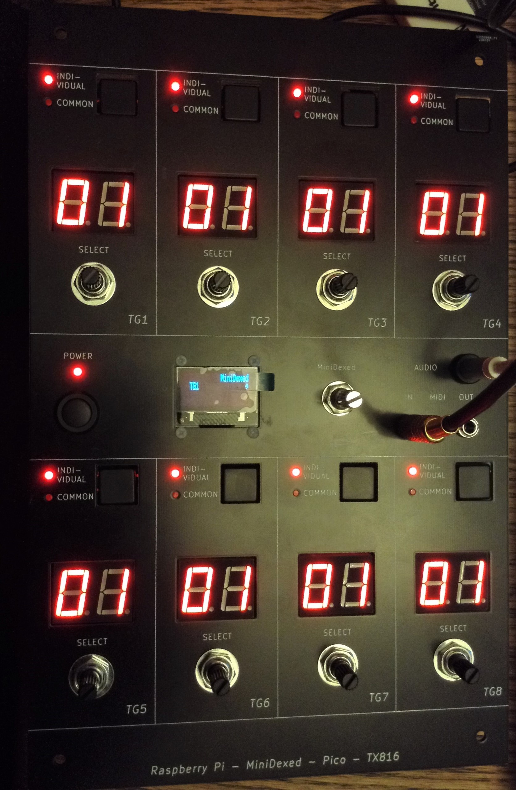
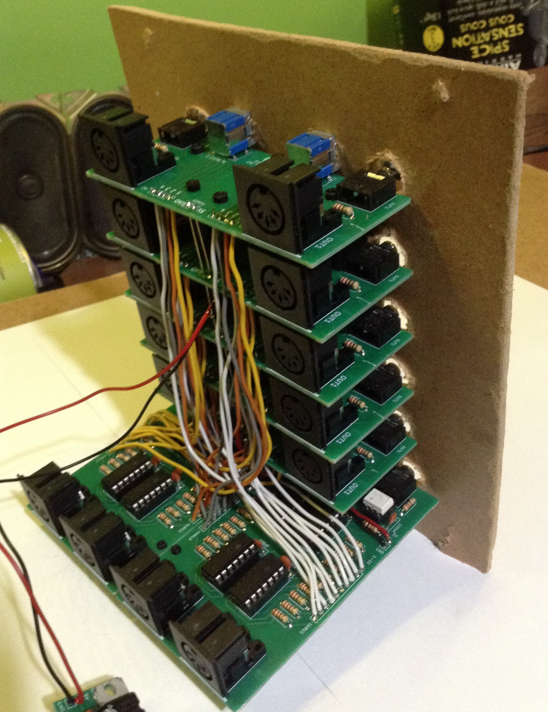
- MiniDexed TX816 – Design and Build
- A Raspberry Pi Pico based TX816 Style IO panel for MiniDexed running on a Raspberry Pi 3 or 4.
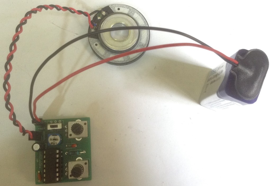
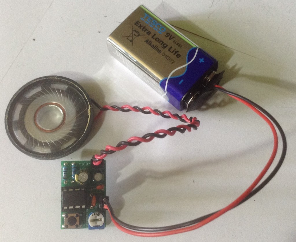
- Atari Punk Console – Design and Build
- A simple version of the classic electronic noise-making machine.

- Korg Volca Modular MIDI to CV – Design and Build
- A MIDI to CV converter that is particularly suited for use with a Korg Volca Modular.

- Prototyping Pedal – Design, Build and Usage Notes
- A prototyping platform for experimenting with microcontrollers and guitar pedals.

- Baby 8 Style Step Sequencer – Design and Build
- A Baby 8 style step sequencer designed to be used with my ESP32 Educational Synth Thing.

- Bespoke PCB for my “Krell” like display – Design and Build
- Supports a standalone 3D printed unit or EuroRack format.

