Following on from my Arduino and AY-3-8910 experiments, one thing I wanted to do was to try to hook up several AY-3-8910 devices and see if I could stack up the polyphony a little. But that is a lot easier without jumper wires, hence this PCB to support some more experiments with an Arduino Nano.
Warning! I strongly recommend using old or second hand equipment for your experiments. I am not responsible for any damage to expensive instruments!
If you are new to electronics and microcontrollers, see the Getting Started pages.
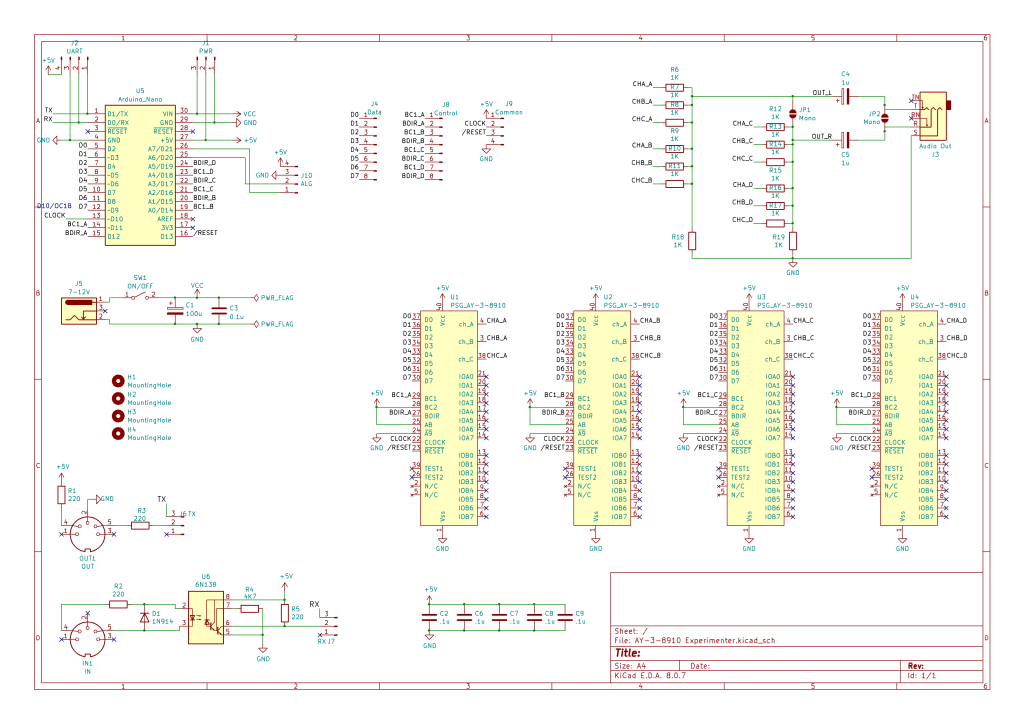
The Circuit
This borrows heavily from existing designs on the Internet, notably:
- https://github.com/GadgetReboot/AY-3-8910
- https://github.com/electrified/rc2014-ym2149
- https://dogemicrosystems.ca/wiki/Dual_AY-3-8910_MIDI_module
I’ve changed the pin connections to the Arduino slightly, to simplify the options for direct PORTIO, but also need to allow for some means to address each AY-3-8910 individually.
There are several options for this:
- Utilise the A8 and /A9 additional address lines somehow.
- Note that there are a number of “inactive” combinations of BC1, BC2 and BDIR.
I went with using the “fix BC2 high” redundancy in the address scheme. This means that the BC1, BC2 and BDIR combinations I’m going to rely on are as the “bus control with no redundancy” options as follows:
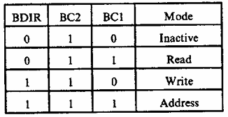
If I have an independent BC1 and BDIR for each device, then unused devices will be inactive when both signals are LOW.
In terms of audio out, I’ve used a simple passive mixer to combine all three channels from all four devices and sent it to a 3.5mm audio jack via a capacitor to remove the DC bias. I’ve sent two devices to the left channel and two to the right, but there are solder jumper options to combine them all into a single mono output either to both channels or just the tip (left).
I’ve also included a 5V MIDI IN and OUT circuit off UART0 and a barrel jack connected to the Arduino Nano VIN pin.
And as there were two analog pins spare (A6, A7) I took them, along with the UAR, to pin headers.
All control, data and common signals for the AY-3-8910s are sent to pin headers too, so there is an option of driving the AY-3-8910s directly. This will require a direct 5V power input though, as there is no on-board regulator other than that built into the Arduino.
Even though I’m using an Arduino Nano with A0-A7, I can’t use those exclusively for the BC1, BDIR connections as A6 and A7 cannot be used as digital IO pins, unlike all the others. I’ve also had to swap the clock signal from D9 to D10, which means swapping the PWM output from OC1A to OC1B.
Well, technically I didn’t have to, but I did it to make an easier mapping of the AY D0-D7 onto the Arduino D2-D9. I need to avoid D0 and D1 as they are the UART and are connected to the MIDI circuit.
Errata and Update
One thing I hadn’t realised with the first design (and subsequently with the PCB below) is that the output stage of the AY-3-8910 requires a pull-down to GND resistor. This can be seen in the example schematic in the datasheet:
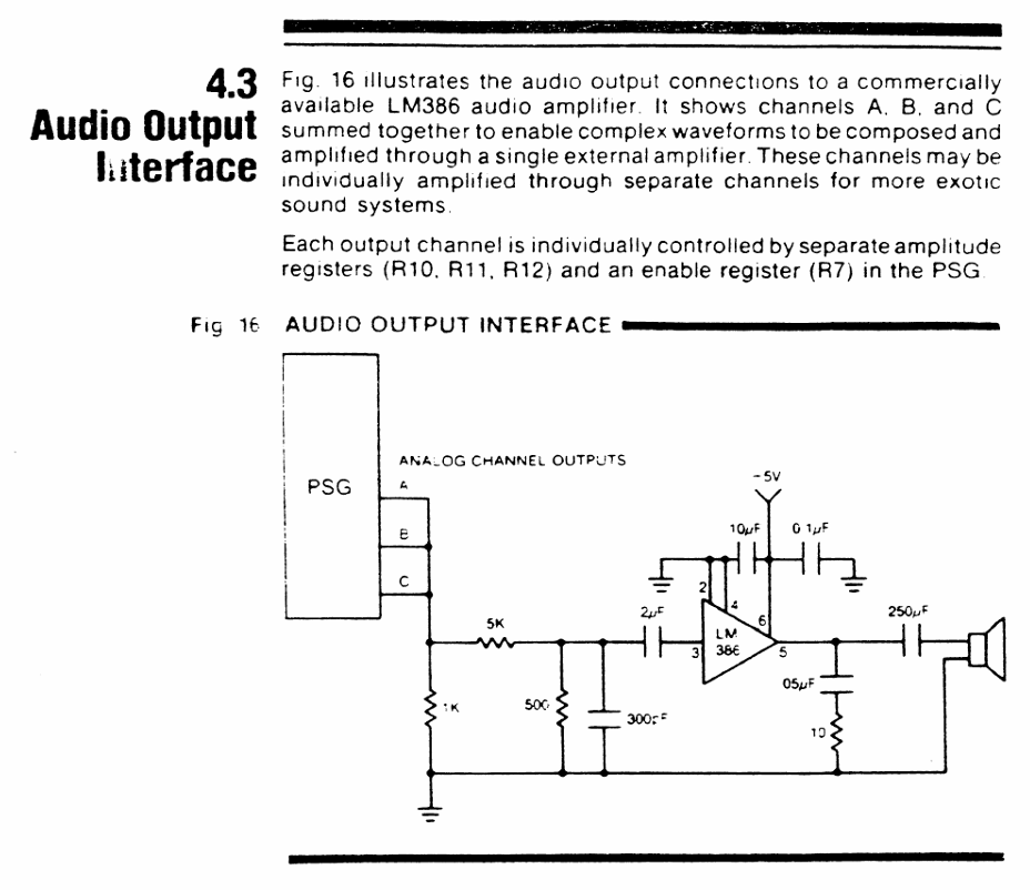
But because it isn’t mentioned in the text, I ignored it. I was going for a passive mixer arrangement and wanted to combine one set of outputs with the outputs for the other three chips.
But it turns out that without that pull-down resistor, the outputs remain HIGH. It took me a lot of head-scratching to work out what wasn’t working…
Going back to various other schematics I’ve found, I can see it is present on all of those too. Here is the audio output stage from Gadget Reboot’s board:
The complication for me is should the pull-down go before or after the passive mixer signals? The RC2014 AY card has one per output channel prior to the mixer resistors:
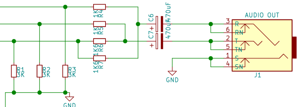
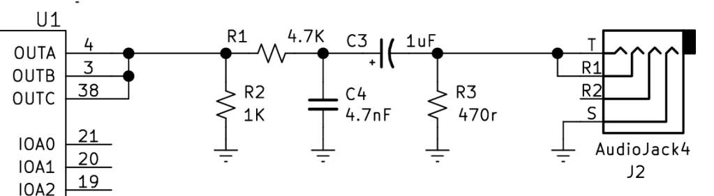
Given that I already have the PCBs made, I experimented and went with adding a single pull-down for each of the L and R channels – so one per six resistors. That appears to work.
This change hasn’t made it to the PCB, so a patched workaround is required. It also seems to require a different capacitor to get a usefully functional signal out of the audio jack.
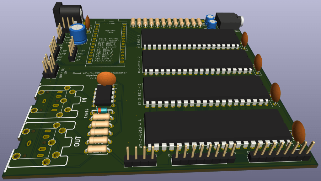
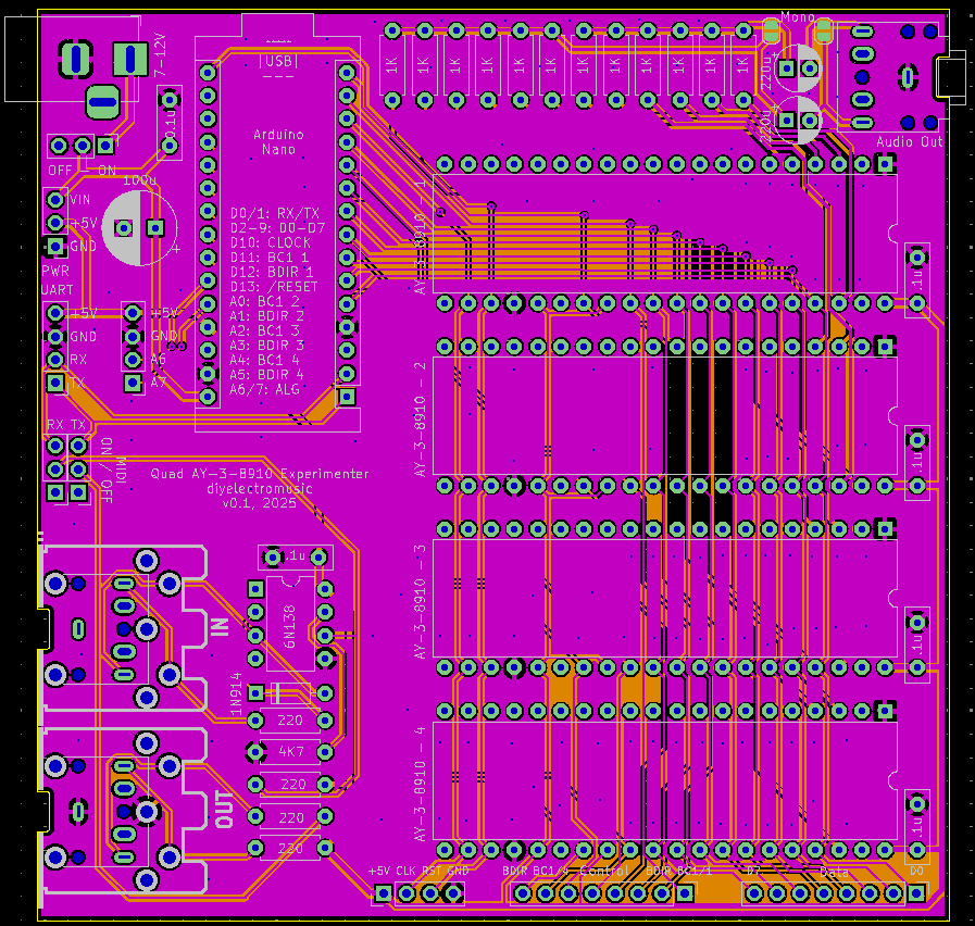
PCB Design
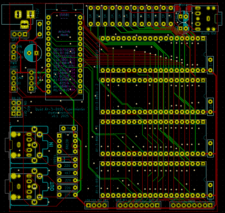
I’m not sure there is a lot to say about this design. Hopefully all signals will function ok.
I’ve included the full GPIO usage table in the silkscreen so hopefully that will save me reaching to the computer for these posts when I’m programming the Arduino.
I originally included four mounting holes but it proved just too much of a challenge to squeeze them in a 100x100mm board, so I decided I’d do without them.
Update: As noted above, two additional resistors to GND are required on the audio output circuit. These can be patched in after the fact (see the build guide for details).
Closing Thoughts
In general the design seems like it will be really useful. Missing the pulldown resistor is annoying, and wasted quite a bit of time, but in my defence, as an electronics novice, there isn’t any documentation I can find as to why it is required.
Kevin
