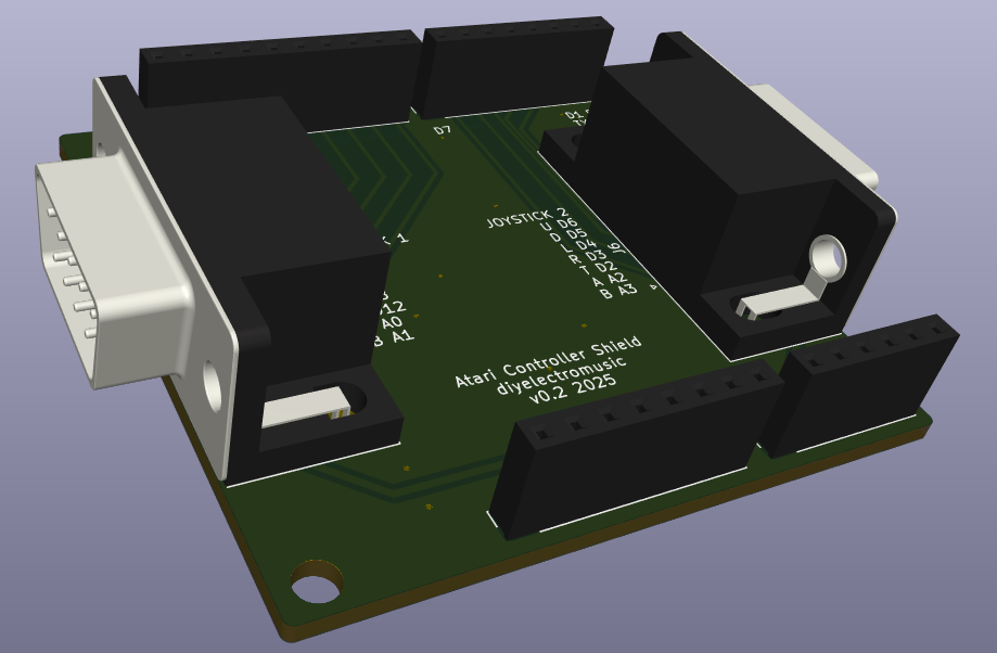
This is an Arduino Uno shield format PCB for hooking up two Atari 2600 style controllers to an Arduino.
Note: this iteration of the design doesn’t really do the paddles very well, but it works fine for joysticks and keypad controllers.
There are some updates here:
- Atari 2600 Controller Shield PCB Revisited
- Atari 2600 Controller Shield PCB Revisited – Part 2
- Atari 2600 Controller Shield PCB Revisited – Part 3
And some sample applications of it in use:
Warning! I strongly recommend using old or second hand equipment for your experiments. I am not responsible for any damage to expensive instruments!
If you are new to Arduino, see the Getting Started pages.
The Circuit
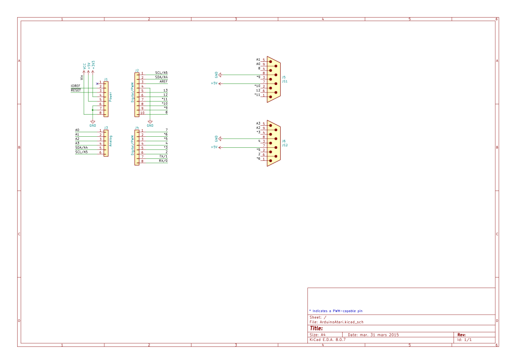
This is a fairly straight-forward mapping of an Atari controller’s pins to Arduino IO pins.
The most comprehensive description I’ve found of what the 9 pins on the D-type connector are is the following. And there are a few other useful references too:
- https://atariage.com/2600/archives/schematics/Schematic_2600_Accessories_Low.html
- https://forums.atariage.com/topic/225470-the-atari-joystick-pinout-common-ground/
- https://www.epanorama.net/documents/joystick/ataristick.html
On driving them with an Arduino, the following are relevant:
- https://hackaday.io/project/170908-control-freak
- https://github.com/nomdeclume/AtariJoysticksPlus
- https://github.com/retrospy/RetroSpy
Standard Joysticks
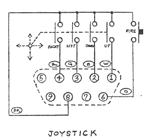
The buttons are pulled high, connected low when the button is pressed. This makes reading the joystick and paddle buttons relatively straight forward.
Paddles
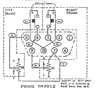
The analog paddle inputs are a little more complicated. On first inspection, I thought they were effectively potentiometers across 5V and GND, but actually it turns out they are 1M variable resistors across 5V and the wiper. This means that reading them is a little more complex.
To read them using a simple ADC method, it is possible to include a second resistor between the controller pin and GND, creating a voltage divider that can then be read via the ADC. The smaller the second resistor, the more of the voltage range will be covered.
But it isn’t a typical voltage divider. As R1 changes, the percentage of R2 changes too, so whilst a small R2 gives more of the voltage range (closer to 0V up to 5V), the change is less linear.
Here are some graphs showing the output voltage profile for different R2 values.
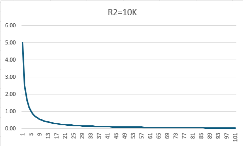
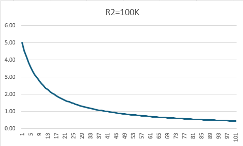
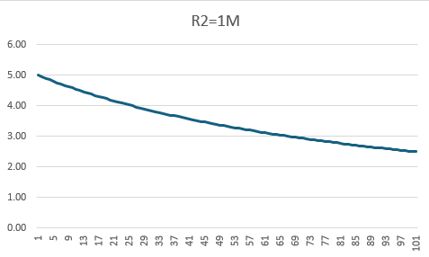
So 1M (which of course matches the resistance already in the paddle controller pot) gives the most linear response, but it has the following properties:
- Read value = 0V -> controllers not present.
- Read value between 2.5V and 5V -> controller present and being used.
The actual Atari circuit appears to have a 1.8K resistor into the microcontroller pin with a 68nF capacitor to GND (follow the circuit from pins 5 and 9 here). From some of the above links for using paddles with an Arduino it appears the basic algorithm for reading the paddles is to time the charging and discharging of the capacitor.
There is no facility on this version of the board to allow for the addition of a capacitor and a resistor. It is possible to include a resistor to GND in some cases, but really the use of this board with paddles is quite sub-optimal!
Keypads
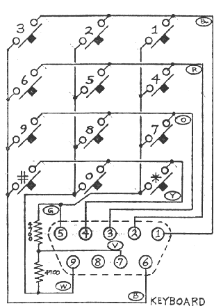
When used with a keypad, the four direction buttons are mapped to rows, and the two paddle inputs (pulled up in the controller to 5V) and trigger is used for the columns.
Arduino GPIO
From all this, we can derive the following table and map that over to Arduino IO pins. I’ve added two 9-pin connectors, so they are mapping onto two sets of Arduino pins.
| Atari Pin | JoyStick | Paddles | Keypad | Arduino port 1 | Arduino port 2 |
| 1 | UP | ROW1 | 11 | 6 | |
| 2 | DOWN | ROW2 | 10 | 5 | |
| 3 | LEFT | TRIGGER A | ROW3 | 9 | 4 |
| 4 | RIGHT | TRIGGER B | ROW4 | 8 | 3 |
| 5 | PADDLE B | COL1 | A1 | A3 | |
| 6 | TRIGGER | COL3 | 12 | 2 | |
| 7 | 5V | 5V | 5V | ||
| 8 | GND | GND | GND | ||
| 9 | PADDLE A | COL2 | A0 | A2 |
As A0-A3 can be used as either digital or analog inputs this makes decoding the controllers particularly easy (paddles not withstanding) once it is known what kind of controller is attached.
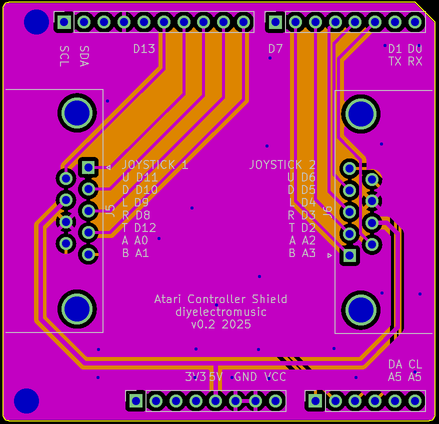
PCB Design
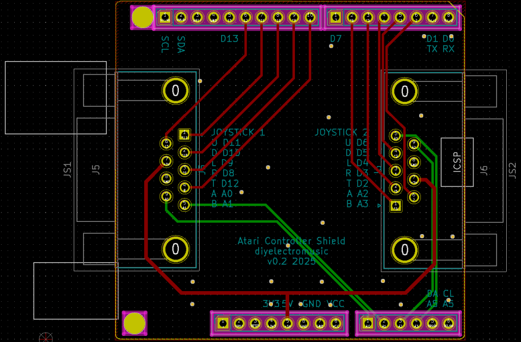
The PCB design is quiet straight forward. The IO pins have been chosen for easy routing. I’ve used footprints for the two controller connectors that matched the PCB-mount connectors I’ve been able to pick up fairly cheaply.
All unused Arduino IO pins have been labelled on the board for ease of use. The following are all available:
- D0/D1 – RX/TX
- D7, D13
- A4, A5 – SDA/SCL
This leaves options for UART, I2C, digital and analog IO.
As already mentioned, no provision has been included for sensible decoding of the paddles. That will have to come in a future version.
Closing Thoughts
In the first iteration of this board, although it is a pretty straight forward board, I’d managed to use the footprints for the socket version of the 9-pin connectors and not the pins version.
This meant that when I got the boards back, the pins were all back to front!
I had a quick re-spin of the board, including swapping the pins associated with UDLR over so that routing remained fairly trivial.
If I’d looked at the 3D version of the board prior to sending it off, I might have noticed. Oh well.
The whole thing with the paddles was because I’d mis-read the schematic for the controllers and made the assumption that they were wired between 5V and GND in a common potential divider format.
It wasn’t until the boards came back and the paddles weren’t working that I looked a bit deeper and spotted the misunderstanding. Oh well.
Kevin
