This is a follow up post to Part 2 expanding on the code and adding in some of the alternative control options I mentioned.
- Part 1 – getting to know the devices and testing them out.
- Part 2 – adding MIDI to the LED ring and I2C encoder.
- Part 3 – adding normal encoder, plain potentiometer, and endless potentiometer control.
- Part 4 – revisits the idea with Waveshare Zero format devices and adds USB MIDI.
Warning! I strongly recommend using old or second hand equipment for your experiments. I am not responsible for any damage to expensive instruments!
If you are new to Arduino, see the Getting Started pages.
Parts list
- Arduino Uno/Nano.
- DuPPa small RGB LED Ring.
- 10K potentiometer.
- KY-040 rotary encoder module.
- Bespoke hook-up wires (available from duppa.net).
- Breadboard and jumper wires.
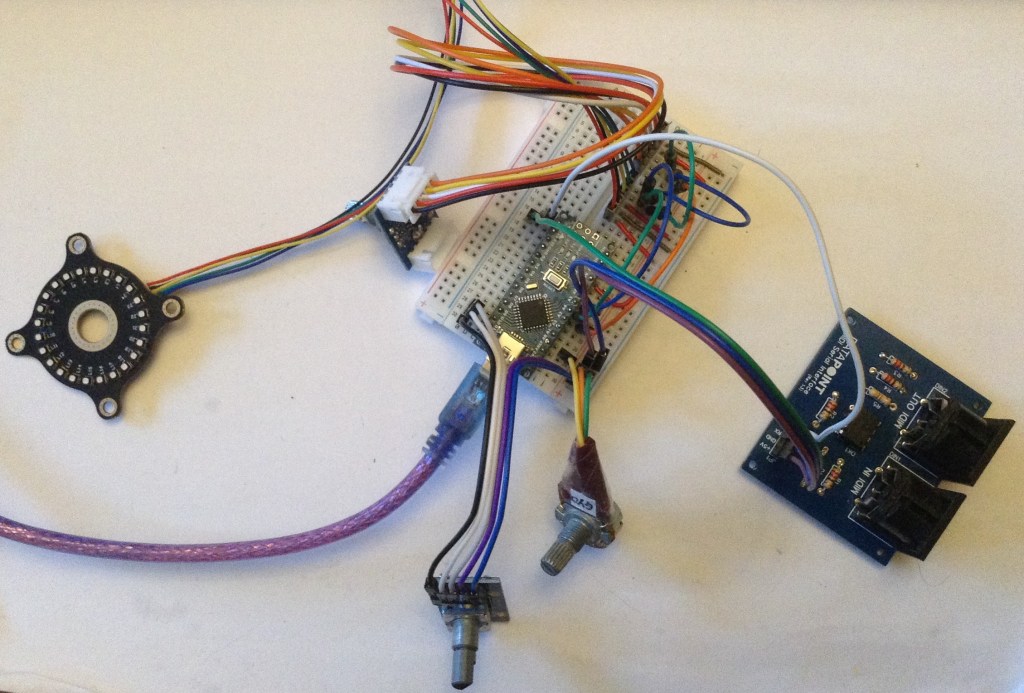
The Circuit
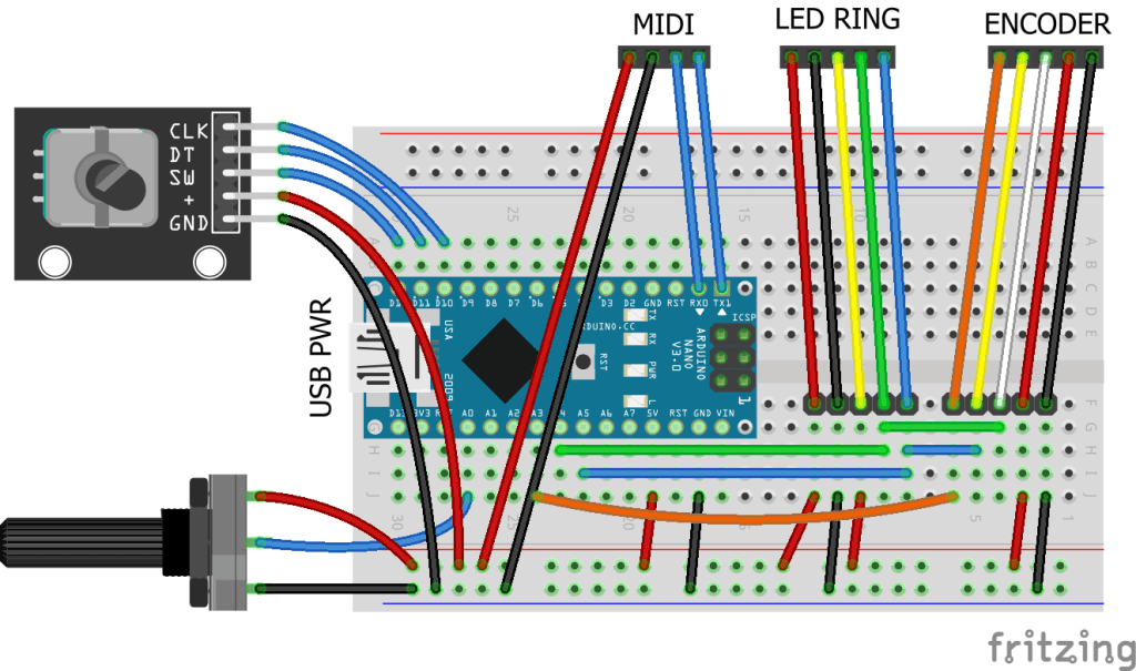
This circuit shows all three control options on the same diagram, but naturally use whichever one you require. There are the following three options:
- Duppa I2C Encoder (from the previous project) on A4, A5 (SDA, SCL).
- Plain potentiometer on A0.
- Rotary encoder on D10, D11, D12.
In addition to the I2C LED Ring on A4, A5 (SDA, SCL) of course.
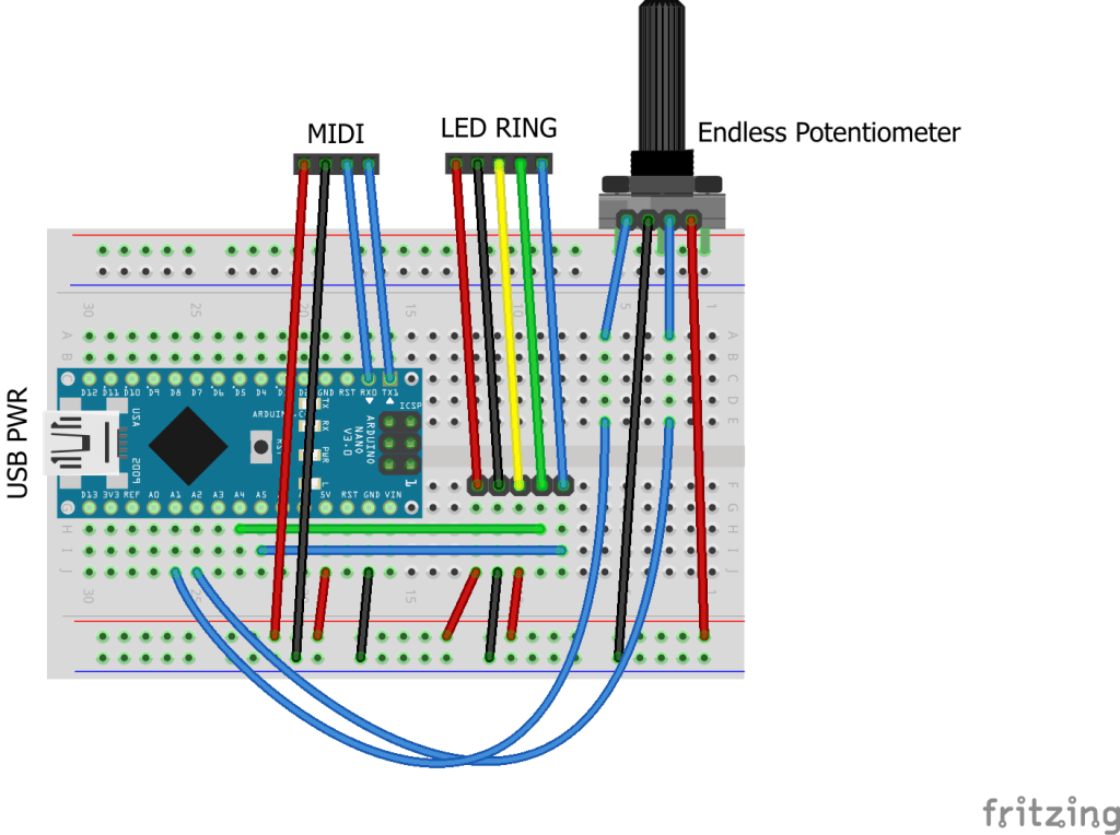
Here is a separate diagram for the endless potentiometer. I can be used alongside the above, but I’ve drawn it on its own for clarity.
Mine has the pins in the following order: Wiper A, GND, Wiper B, VCC.
The Code
This uses the code from Part 2 as a starting point and adds in some additional features.
The main aim is to add additional control options and then make them selectable in code. There are several definitions at the top of the file. One of them should be uncommented to enable that control option.
//#define CC_ENCODER
#define CC_POTENTIOMETER
//#define CC_I2CENCODER
//#define CC_ENDLESSPOT
Each control method will have some associated functions, but the interface will be hidden away behind these definitions and called from the main code, something like the following.
#ifdef CC_ENCODER
#include <librarycode.h>
... control specific definitions ....

void encSetup() {
// Control specific setup code
}

void encLoop() {
// Control specific loop code
}
#else
void encSetup() {}
void encLoop() {}
#endif
If that control option is not enabled, then it will just end up with the two empty functions.
Normal Potentiometer
This is fairly straightforward. I’m using the averaging technique I’ve mentioned before (details here) and include a counter so that the pot isn’t read on every scan, otherwise it slows down all other processing significantly.
The pot reading is scaled down to 7-bits from the default 10-bit value with a bitshift.
I’ve opted to have a jump if the CC value is updated over MIDI rather than anything more sophisticated, as that is probably the simplest.
All the same display options are available as used previously: one LED per CC; scaled to multiples of the ring size; or scaled to a single ring.
This works quite well with all of them, but probably makes most sense when the MIDI CC range is scaled to a single revolution of the LED ring.
CC_WRAP has no effect when used with a normal potentiometer, as the pot itself does not wrap around.
Rotary Encoder
This is using the same encoder library I’ve used before in my Arduino MIDI Rotary Encoder Controller. This makes the scanning code relatively straight forward.
I’ve refactored out the increment/decrement functions from the I2C encoder code into midiCCIncrement and midiCCDecrement, so these can now be used by both encoder options.
These encoder modules are often switched, but I’m not making use of the switch here.
Once again, all the same display options are available: one LED per CC; scaled to multiples of the ring size; or scaled to a single ring. CC_WRAP can be on or off.
Endless Potentiometer
There is a detailed discussion of how these work here: https://hackaday.io/project/171841-driveralgorithm-for-360-deg-endless-potentiometer
My initial thought was that I could just use one of the wipers, assuming it would go from 0 to full resistance and immediately back to zero, but they don’t – they gradually go from 0 to full resistance and then gradually back to 0 again. See the diagram in the above link.
This means that some processing is required to get a single reading out of them, so I ended up using a library from here:
Well actually, I ended up using the slight variant of the library as used on the “Ottopot” MIDI controller, which can be found here:
In my case I just dropping in the endlesspotentiometer.cpp/h files into my Arduino sketch (swapping any includes from <> to “” in the process). There was one reference to main.h that needed removing, and it required a definition of MAX_POT_VALUE which is 1023 for an Arduino Uno.
Then the code is fairly straight forward as the library is able to give an indication of direction and how much the pot has moved.
One thing to watch out for – I wanted this to be able to act on midiCC in a relative manner, replication the benefits of an encoder, but with a potentiometer, so I needed to know how much the pot had changed and then add that to the current midiCC value, rather than set it directly.
To do this I allowed midiCCIncrement/Decrement to take a parameter – how far to increase or decrease midiCC.
The core code for handling the endless pot was thus:
endpot.updateValues(epot1.avgeAnalogRead(PIN_EALG_1),
                    epot2.avgeAnalogRead(PIN_EALG_2));
if (endpot.isMoving) {
  if (endpot.direction == endpot.CLOCKWISE) {
    midiCCIncrement(endpot.valueChanged);
  } else if (endpot.direction == endpot.COUNTER_CLOCKWISE) {
    midiCCDecrement(endpot.valueChanged);
  }
}
I also turned the potentiometer averaging code into a class of its own so I could also use it here for both analog readings of the endless pot.
It took a bit of experimentation with the sensitivity and threshold settings and how they interacted with the frequency of reading, but I’ve ended up with something that seems to work ok for me.
Summary
Although at the start I said that one of the options should be commented out to select it, in reality, if the devices are all on separate IO pins, then actually they can all be enabled at once.
And it does seem to work pretty well, with all four methods: I2C encoder, plain encoder, potentiometer – all interacting as you might expect they would.
Closing Thoughts
I was quite surprised how usable everything was with all four input methods enabled. I probably wouldn’t recommend it for typical use, but it was a bit of fun.
It is particularly satisfying to sweep through the entire range using the pot with “one LED per CC” enabled, even though scaling a single ring to the potentiometers range makes more sense (to me).
At some point I will try to get several controls up and running.
Kevin