Here are the build notes for my AY-3-8910 Experimenter PCB Design.
Warning! I strongly recommend using old or second hand equipment for your experiments. I am not responsible for any damage to expensive instruments!
If you are new to electronics and microcontrollers, see the Getting Started pages.
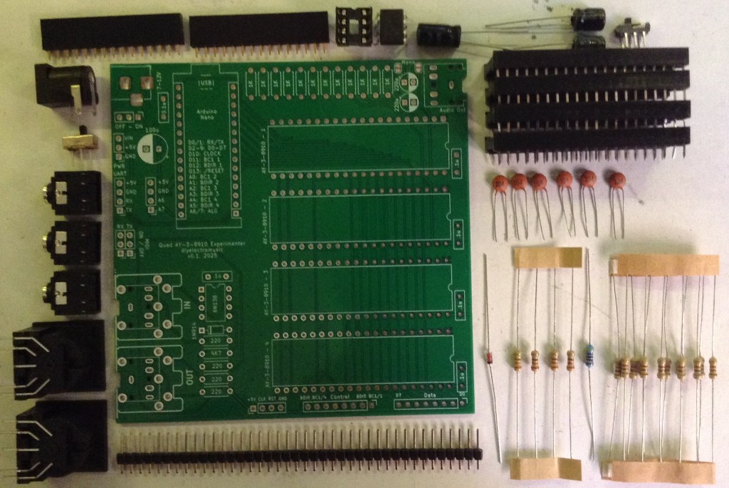
Bill of Materials
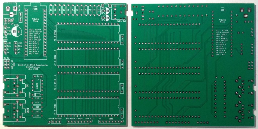
- AY-3-8910 Experimenter PCB (GitHub link below)
- Arduino Nano
- Up to 4x AY-3-8910 40-pin DIP devices (see notes here on obtaining devices: Arduino and AY-3-8910)
- 1x 6N138 optoisolator
- 1x 1N4148 or 1N914 signal diode
- Resistors: 4x 220Ω, 1x 4K7, 14x 1K
- 6x 100nF ceramic capacitors
- 2x 1uF electrolytic capacitors (the PCB has 220uF on the sinkscreen)
- 1x 100uF electrolytic capacitor
- Either: 3x 3.5mm TRS PCB mount sockets
- Or: 1x 3.5mm TRS PCB mount sockets and 2x 180 DIN PCB mount sockets
- 1x 2.1mm barrel jack socket
- 2x 15-way pin header sockets
- 4x 40-way wide DIP sockets
- Pin headers
- Optional: 1x SPDT, 1x DPDT both with 2.54mm pitch connectors
- Optional: 1x 8-way DIP socket
Build Steps
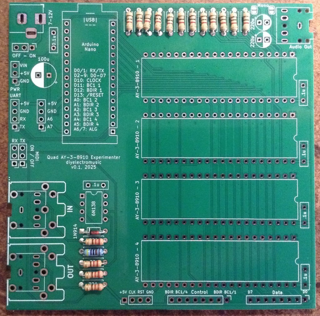
Taking a typical “low to high” soldering approach, this is the suggested order of assembly:
- All resistors and diode.
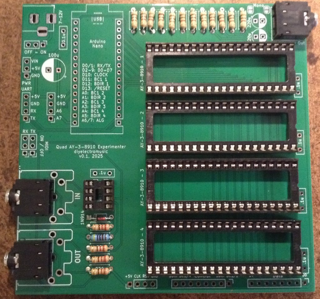
- DIP and TRS socket(s).
- Disc capacitors.
- Switches (if used).
- Electrolytic capacitors.
- 15-way pin header sockets.
- Barrel jack socket.
- DIN sockets (if used).
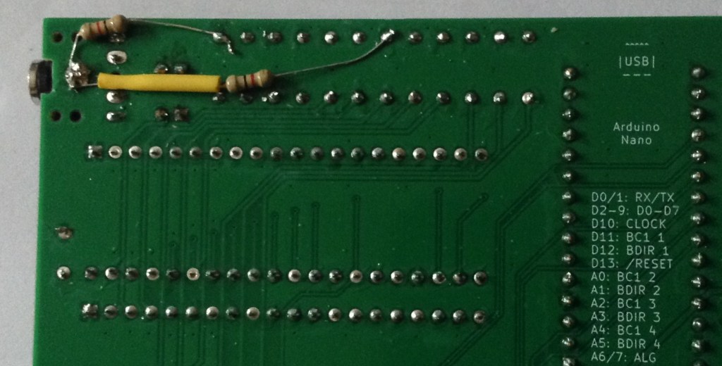
It is necessary to add two additional 1K resistors as patch-links on the underside of the board. Details below.
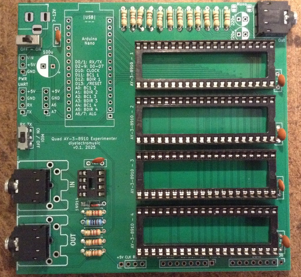
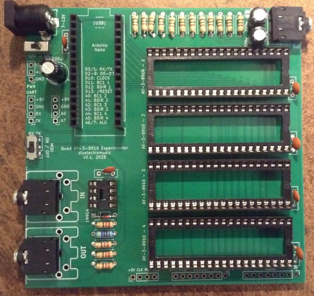
Here are some build photos.
The DIP sockets should go on next before the TRS sockets.
Pin headers and jumpers could be used for the MIDI on/off switch. The power switch could be bypassed with a wire link if not required.
There are a number of optional pin header breakouts: power, UART, additional IO and all the IO for the four AY-3-8910 chips. For this build I’m not populating those.
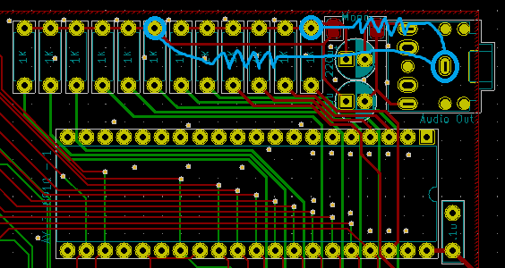
Errata Fixes
As mentioned in the design notes, two additional resistors must be added to pull the audio outputs to GND as part of the output/mixer circuit. I used two additional 1K resistors.
These can be added to the underside of the board as shown below.
Testing
I recommend performing the general tests described here: PCBs.
Once everything appears electrically good, here is a test application that will play a chord on each of the devices at a different octave. If this works it should be possible to hear all 12 notes in the four chords across four octaves sounding.
Find the code here: https://github.com/diyelectromusic/sdemp/tree/main/src/SDEMP/ArduinoAY38910QuadTest
PCB Errata
As already mentioned there are the following issues with this PCB:
- The two 220uF capacitors should be replaced with 1uF capacitors.
- Two additional resistors need to be patched into the audio output circuit.
Enhancements:
- None
Sample Applications
Here are some applications to get started with:
- (on their way)
Closing Thoughts
It took quite a long time to realise the issue with the output channels. For ages, it appeared that the interface to the chip just wasn’t functioning correctly. With hindsight, some kind of register read/write test would have confirmed that a lot earlier.
It was only when going back to the schematics of other designs and recognising that the output was always HIGH did the penny drop that the additional resistor was required. Then there was some experimentation to find something that would work with my board and not cause issues in use.
But it seems like I got there in the end. Now I can get on with doing something a little more interesting MIDI and music wise.
Kevin

