Here are the build notes for my Waveshare Zero Multi Display PCB.
Also see the Waveshare Zero Multi Display PCB – Expander Board.
Warning! I strongly recommend using old or second hand equipment for your experiments. I am not responsible for any damage to expensive instruments!
If you are new to electronics and microcontrollers, see the Getting Started pages.
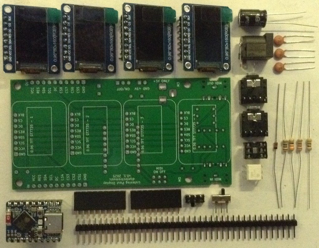
Bill of Materials
- Waveshare Zero Multi Display PCB (GitHub link below)
- Waveshare Zero format board – e.g. ESP32S3 or RP2040
- 1x H11L1 optoisolator
- 1x 1N4148 or 1N914 signal diode
- 4x SPI 0.96″ 80×160 (RGB) IPS TFT displays
- Resistors: 1×10Ω; 1x 33Ω; 1x 220Ω; 1x 470Ω
- Capactitors: 3x 100nF ceramic; 1x 100uF electrolytic
- 2x 3.5mm stereo TRS sockets (see photos and PCB for footprint)
- 1x 2.1mm barrel jack socket (see photos and PCB for footprint)
- 2x 9-way pin header sockets
- Optional: 4x 8-way pin header sockets – strongly recommended. PH5.0 “short” headers are best.
- Optional: 1x 6-way DIP socket – recommended
- Pin headers/jumpers
- Optional: 1x DPDT slider switch with 2.54mm pin footprint
- Optional: 1x SPDT slider switch with 2.54mm pin footprint
Build Steps
Taking a typical “low to high” soldering approach, this is the suggested order of assembly:
- Diode then resistors.
- DIP socket (if used) and TRS sockets.
- Disc capacitors.
- Slider switches (if used).
- 9-way pin header sockets for Waveshare Zero.
- Electrolytic capacitor.
- Barrel jack sockets.
- On rear: 8-way pin header sockets (if used) or displays.
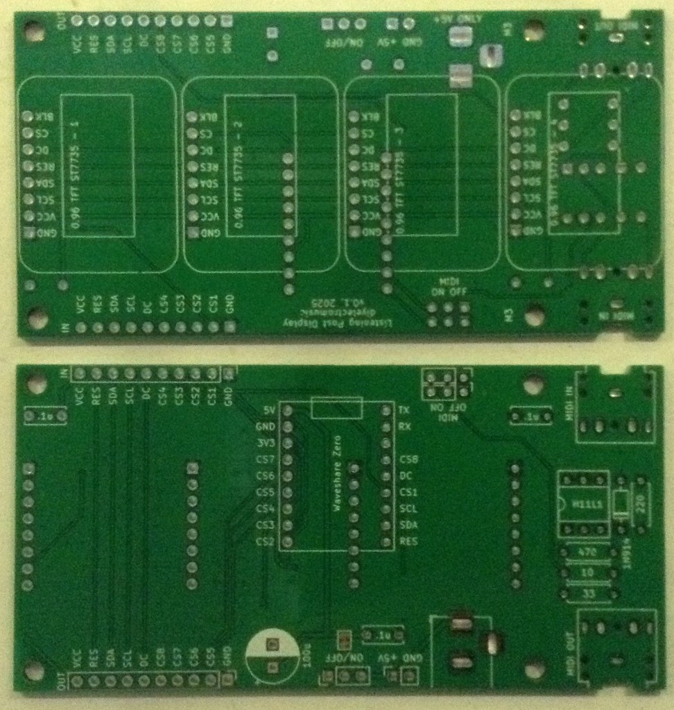
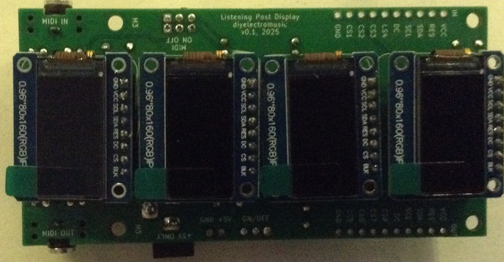
Note: all the components apart from the displays (and their sockets if used) are on one side and the displays are on the other. The silkscreen reflects the side of the components.
Here are some build photos.
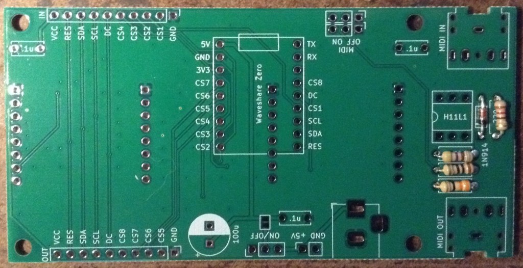
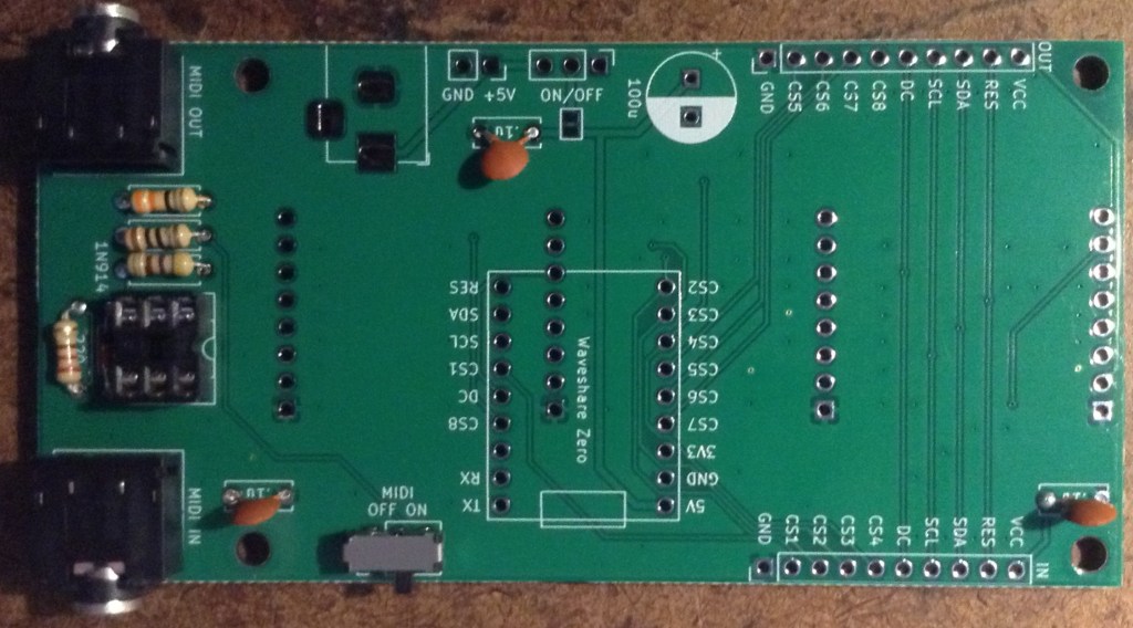
If slider switches are used for MIDI, then as shown above they can be added a this stage too. If pin headers and jumpers are used, then it might be worth waiting until the other header sockets are added. If the ability to disable MIDI isn’t required, then wire jumpers can be soldered on instead to make a permanent connection.
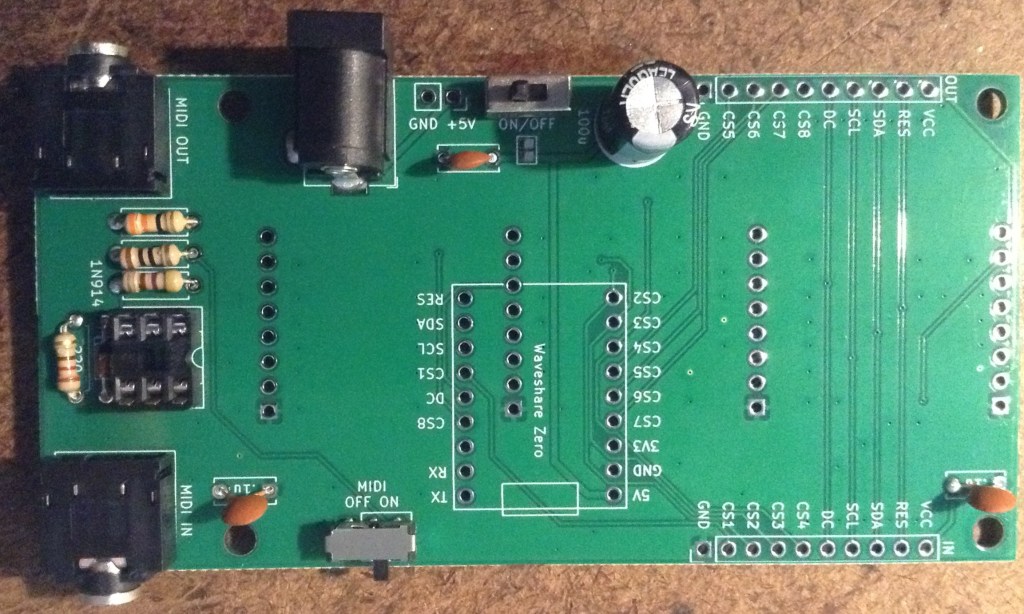
There are a few options around power:
- Use a barrel jack or pin jumper headers. These are both 5V only however as there is no power regulation in this version (it is an option in the schematic, but not the actual PCB).
- An optional on/off switch can be used as long as it has 2.54mm pitch pin connections.
- Note: the solder bridge jumper can be ignored. It is not relevant on a PCB with no regulator.
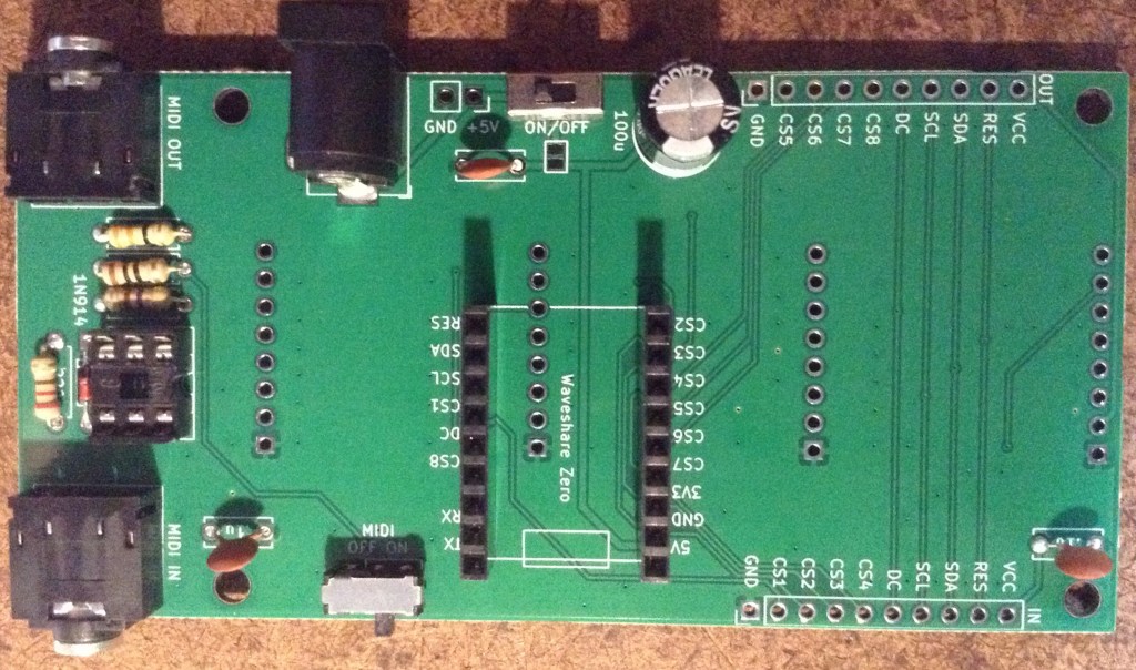
It is strongly recommended that 8-way pin header sockets are used for the displays too. I used PH5.0 height headers, which are shorter than the usual ones.
If the displays are to be soldered directly, then it is strongly recommended that they are tested in isolation first, as there are a number of different types and in my experience cheap ones might not always work on arrival.

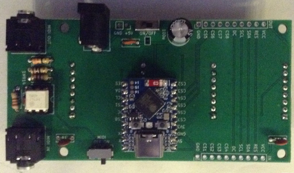
The orientation of the Waveshare Zero and displays is shown below.
It is possible to use M2 spacers to support the displays. For my PH5.0 sized headers, I found that a 6mm spacer, 6mm screw and two nuts gave me the right height to level out each display when plugged in.
Testing
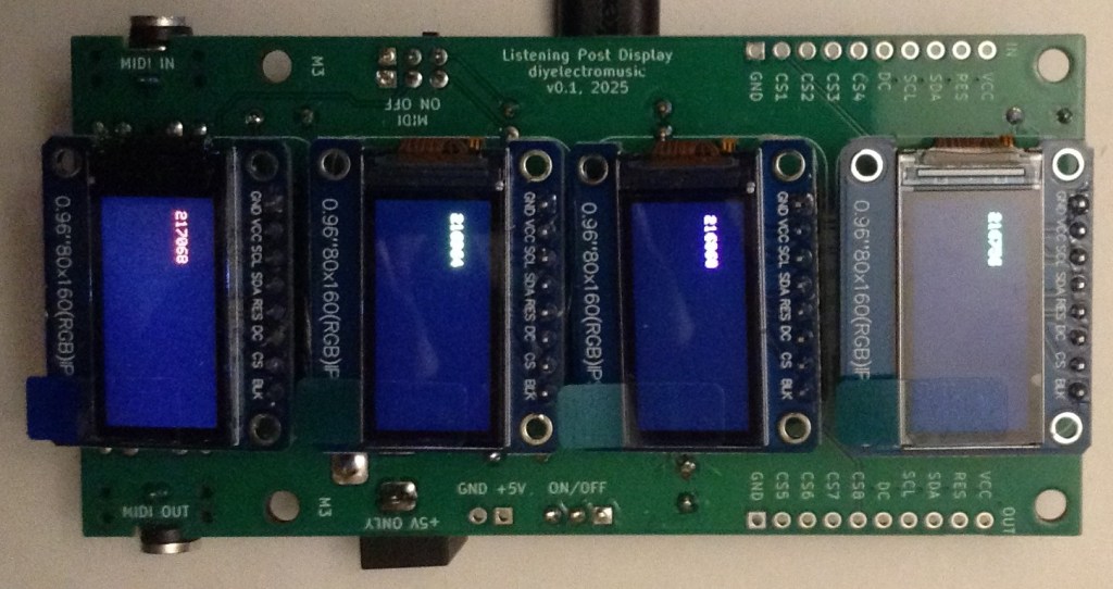
Even before the build is started, it is worth testing the displays to be used. When I first assembled and tested my first board, I had the following:
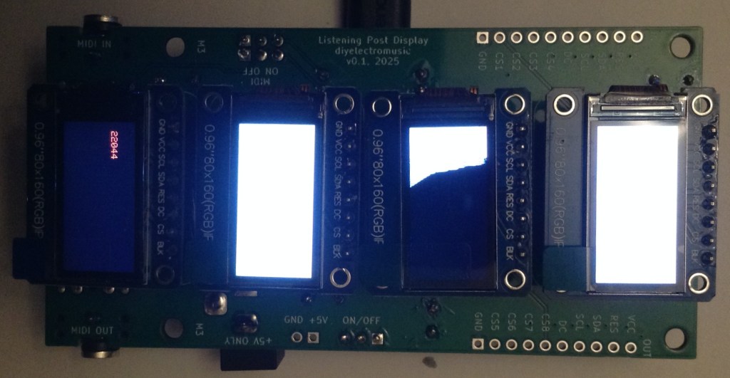
One of the displays was inverted compared to the others, and one had arrived with the screen cracked. At this point I was pleased I’d chosen to use pin header sockets for the displays…
Once built I recommend performing the general tests described here: PCBs.
The using the sample applications mentioned below it should be possible to test the following in turn:
- MIDI IN and OUT.
- Four display.
PCB Errata
There are the following issues with this PCB:
- None at present.
Enhancements:
- I avoided added holes to mount the displays at the time, but now I’m thinking adding the holes on the non-pin header side of the displays would have been really useful.
- Having now seen the completed PCBs, I could probably have left space for a regulator, especially one of those DC-DC converter regulator replacements that doesn’t require a heatsink.
- I should consider adding a 3V3 regulator too rather than driving all the displays through the Waveshare Zero’s onboard 3V3 regulator.
Sample Applications
The GPIO layout for the PCB with various Waveshare Zero boards is given below.
| Function | WSZ Pin | RP2040 | ESP32-C3 | ESP32-S3 | |
| VCC | Power | H1 P3 | 3V3 | 3V3 | 3V3 |
| GND | Ground | H1 P2 | GND | GND | GND |
| RX | MIDI IN | H2 P2 | GP1 (U0/RX) | GP20 (U0/RX) | GP44 (U0/RX) |
| TX | MIDI OUT | H2 P1 | GP0 (U0/TX) | GP21 (U0/TX) | GP43 (U0/TX) |
| DC | Data/Command | H2 P5 | GP4 | GP10 | GP11 |
| RES | Reset | H2 P9 | GP8 | GP6 | GP7 |
| SDA | Data (MOSI) | H2 P8 | GP7 | GP7 | GP8 |
| SCL | Clock (SCLK) | H2 P7 | GP6 | GP8 | GP9 |
| CS1 | CS Display 1 | H2 P6 | GP5 | GP9 | GP10 |
| CS2 | CS Display 2 | H1 P9 | GP14 | GP5 | GP6 |
| CS3 | CS Display 3 | H1 P8 | GP15 | GP4 | GP5 |
| CS4 | CS Display 4 | H1 P7 | GP26 | GP3 | GP4 |
| CS5 | CS Ext Display 5 | H1 P6 | GP27 | GP2 | GP3 |
| CS6 | CS Ext Display 6 | H1 P5 | GP28 | GP1 | GP2 |
| CS7 | CS Ext Display 7 | H1 P4 | GP29 | GP0 | GP1 |
| CS8 | CS Ext Display 8 | H2 P4 | GP3 | GP18 | GP12 |
The application described here can be used to test the displays: Arduino with Multiple Displays – Part 2.
A more complete application for up to four (expandable to eight) displays can be found here: Arduino with Multiple Displays – Part 3.
Using a Waveshare Zero ESP32-S3, the following will test the MIDI IN and OUT:
#include <MIDI.h>

MIDI_CREATE_DEFAULT_INSTANCE();

void setup() {
  MIDI.begin(MIDI_CHANNEL_OMNI);
  pinMode (LED_BUILTIN, OUTPUT);
}

void loop() {
  if (MIDI.read()) {
    midi::MidiType type = MIDI.getType();

    if (MIDI.isChannelMessage(type)) {
      midi::Channel  ch = MIDI.getChannel();
      midi::DataByte d1 = MIDI.getData1();
      midi::DataByte d2 = MIDI.getData2();
      switch(type) {
        case midi::NoteOff:
          digitalWrite (LED_BUILTIN, LOW);
          break;

        case midi::NoteOn:
          digitalWrite (LED_BUILTIN, HIGH);
          break;

        default:
          break;
      }
    }
  }
}
Closing Thoughts
This seems to work pretty well. I’ve not really put it through its paces yet, but driving the displays is working and so is MIDI.
I have a specific application in mind, but first I need to see if it is possible to link these boards together to get more displays running. That is explored here Waveshare Zero Multi Display PCB – Expander Board.
Kevin
