Having had a bit of a play with the SP0256A-AL2 Speech Synthesis chip, this post looks at how to drive it directly from an Arduino.
- Part 1 – Basic introduction and getting started
- Part 2 – Arduino programmable clock
- Part 3 – Using a Raspberry Pi Pico as a programmable clock
- Part 4 – Using a HC4046 PLL as the clock
- Part 5 – Using an I2C SI5351 programmable clock
- Part 6 – Adding MIDI

Warning! I strongly recommend using old or second hand equipment for your experiments. I am not responsible for any damage to expensive instruments!
If you are new to Arduino, see the Getting Started pages.
Parts list
- Arduino Uno
- SP0256A-AL2 speech synthesizer chip
- 3.579545 crystal oscillator
- 2x 1KΩ resistors
- 2x 100nF capacitors
- 1x 1uF capacitor
- 1x 3.5mm jack socket
- Breadboard and jumper wires
The Circuit
This is based on several other circuits I’ve found, and reading through the datasheet:
- Arduino + Vintage Speech Chip Instructable: https://www.instructables.com/Arduino-Vintage-Speech-Chip/
- MG005 Speech Synthesizer for RC2014: https://jerryfrost1.wixsite.com/tech/blank-page-4
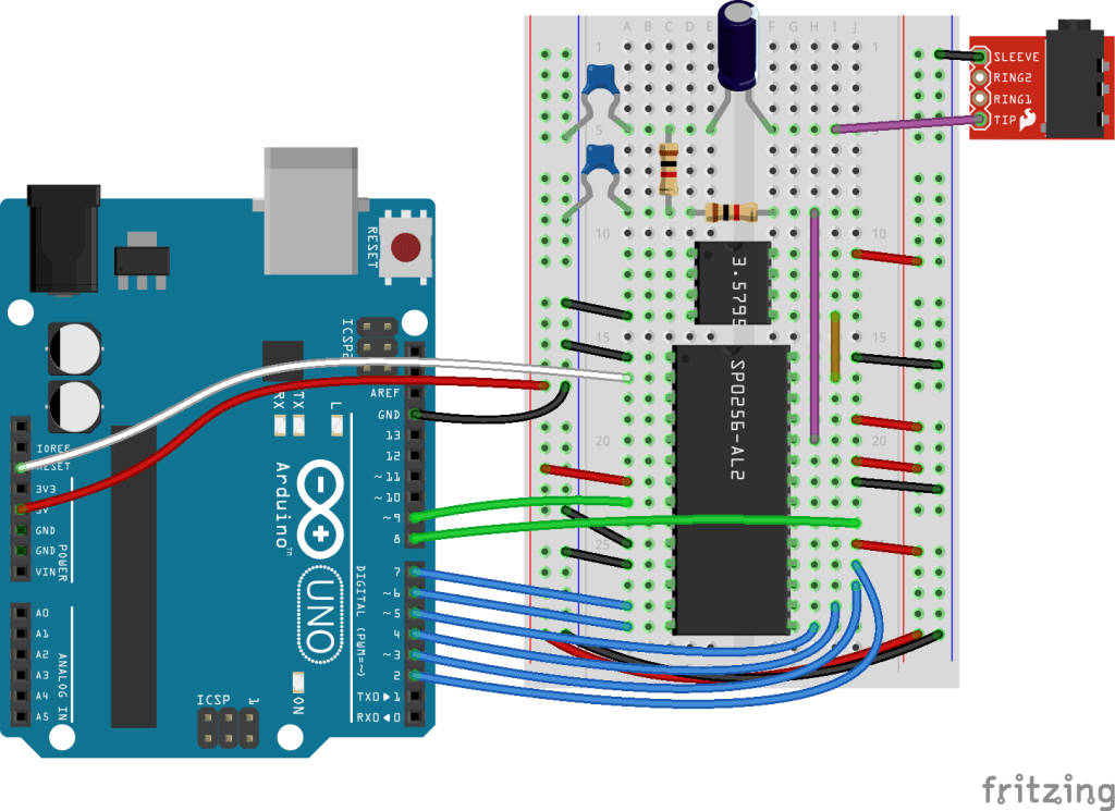
Here are the required connections for the SP0256A-AL2 to the crystal, output circuit and the Arduino:
| GND | 1: VSS | OSC 2: 28 | GND |
| RESET | 2: /RESET | OSC 1: 27 | Crystal OUT |
| N/C | 3: ROM DISABLE | ROM CLOCK: 26 | N/A |
| N/C | 4: C1 | /SBY RESET: 25 | 5V |
| N/C | 5: C2 | DIG OUT: 24 | Audio Filter |
| N/C | 6: C3 | VDI: 23 | 5V |
| 5V | 7: VDD | TEST: 22 | GND |
| D9 | 8: SBY | SER IN: 21 | N/C |
| N/C | 9: /LRQ | /ALD: 20 | D8 |
| GND | 10: A8 | SE: 19 | 5V |
| GND | 11: A7 | A1: 18 | D2 |
| N/C | 12: SER OUT | A2: 17 | D3 |
| D7 | 13: A6 | A3: 16 | D4 |
| D6 | 12: A5 | A4: 15 | D5 |
The datasheet suggests a PWM filter comprising 33K resistors and 22nF capacitors. This creates a significant amount of filtering but results in a very low output signal. The datasheet pushes the output of the filter into an amplifier as shown below.

But for my messing around, I was happy to compromise a little on the filter in order to have a stronger output signal. So I used two 1K resistors and two 100nF capacitors in my filter stage and then connected it directly to a 3.5mm jack socket.
I’m also using a square, 3.579545 crystal oscillator connected to OSC 2, with OSC 1 connected to GND. The pinout of the oscillator is often listed as if it was the four corner pins of an 8-pin DIP package, so pins 1, 4, 5 and 8, with a “dot” next to pin 1, when oriented with the dot to the top left. The pin usage is as follows:
- Pin 1: squared corner next to the dot: not connected
- Pin 4: GND
- Pin 5: Oscillator output
- Pin 8: VCC
As I’ve fixed A7 and A8 to GND, A1 to A6 can map directly onto D2 to D7 which are the 6 higher bits of PORTD on an ATMega328P. Recall that D0 and D1 are the UART, so I’ll be leaving those free.
I originally had /RESET tied permanently to 5V but I was finding the chip wouldn’t always start properly and sometimes got stuck, so I tied it directly to RESET on the Arduino and it seemed to work a lot more reliably at that point.
The Code
The code is relatively straight forward. I need a list of the allophones, which I provide via a series of #define statements, and a list of the corresponding delays between them, which I provide in an array of 16-bit values, using the allophone number as the index.
I’m using direct PORT IO to access the data/A lines of the SP0256A-AL2. This involves shifting the allophone number left by 2 bits to avoid clashing with the UART on D0/D1, whilst preserving the values in D0/D1.
I’ve written two macros, one to handle a write via PORTD and one to check for the STBY signal via D9 on PORTB.
#define pinALD 8
int pinA[6] = {2,3,4,5,6,7}; // Use direct PORT IO
#define SP_OUT(addr) {PORTD = (PIND & 0x03) | ((addr)<<2);}
#define pinSTBY 9
#define SP_CHK() ((PINB & 0x02)!=0x02)
The algorithm required to set an allophone is determined from the datasheet as follows:
WAIT for STBY signal to go HIGH
Set the data on A1-A6 (A7 and A8 are left at GND)
Toggle the /ALD line LOW for between 0.2 and 1.1mS
Wait for the allophones allotted delay
Once again, a sequence of allophones can be determined using the methods described previous in SP0256A-AL2 Speech Synthesis.
Closing Thoughts
It is great to get this working with an Arduino. One thing I’d like to try, is to see if I can clock the chip using the PWM output of the Arduino, in the same way as I did with the AY-3-8910. If so, then I might be able to experiment with varying the clock, which might have some interesting results.
I’d also like to get all this onto a shield PCB at some point too and then I get on to those musical ideas.
Kevin
