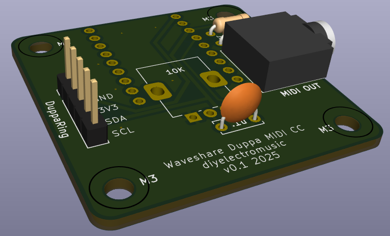
This is the design for a simple carrier PCB for a Waveshare Zero format microcontroller and a Duppa small LED Ring. It is essentially a PCB version of Duppa I2C MIDI Controller – Part 4.
Warning! I strongly recommend using old or second hand equipment for your experiments. I am not responsible for any damage to expensive instruments!
If you are new to microcontrollers, see the Getting Started pages.
The Circuit
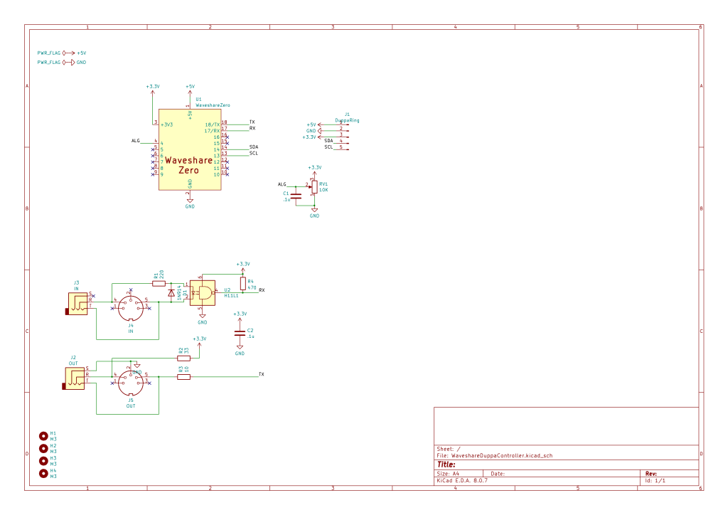
This connects a Waveshare Zero format board to a MIDI IN and OUT interface and a potentiometer. There is a header required to connect to the Duppa Small LED ring.
The following IO pins are used:
| Physical Pin | GPIO: C3, S3, RP2040 | Function |
| 1 | Power | 5V |
| 2 | Ground | GND |
| 3 | Power | 3V3 |
| 4 | GP0, GP1, A3 | Potentiometer |
| 13 | GP9, GP10, GP5 | LED SCL |
| 14 | GP10, GP11, GP4 | LED SDA |
| 17 | GP20, RX, GP1 | MIDI RX |
| 18 | GP21, TX, GP0 | MIDI TX |
For the RP2040 this is using I2C0 and UART0.
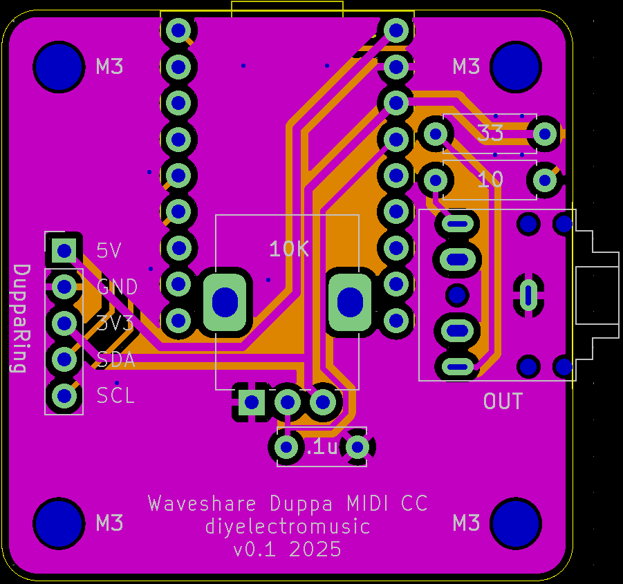
PCB Design
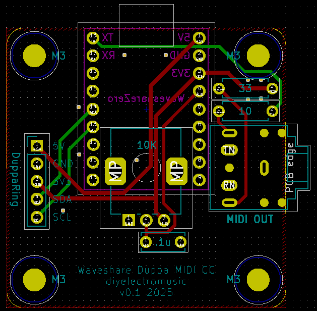
I’ve actually opted not to include MIDI IN functionality in order to keep within a minimal PCB footprint. I’m aiming to have it occupy essentially the same space as one of the small Duppa LED rings itself. I’m also only support MIDI OUT via a TRS jack.
But I have attempted to ensure that both the Waveshare USB socket and TRS socket will protrude enough to be brought out to the edge of a case.
I’ve included a 2.54mm pitch set of header pads that I plan to solder a connecting wire to for the Duppa ring.
Closing Thoughts
I was in two minds about including MIDI IN. It is nice to be able to use this to merge into an existing MIDI stream, but then I also considered that it would probably be used just as a controller in most cases, so went with the small PCB footprint.
I also considered the four control options I’ve experimented with so far. In the end I decided I still liked having an absolute-value potentiometer for a MIDI Controller like this over either a rotary encoder or an endless potentiometer, so that is what I’ve used.
Kevin
