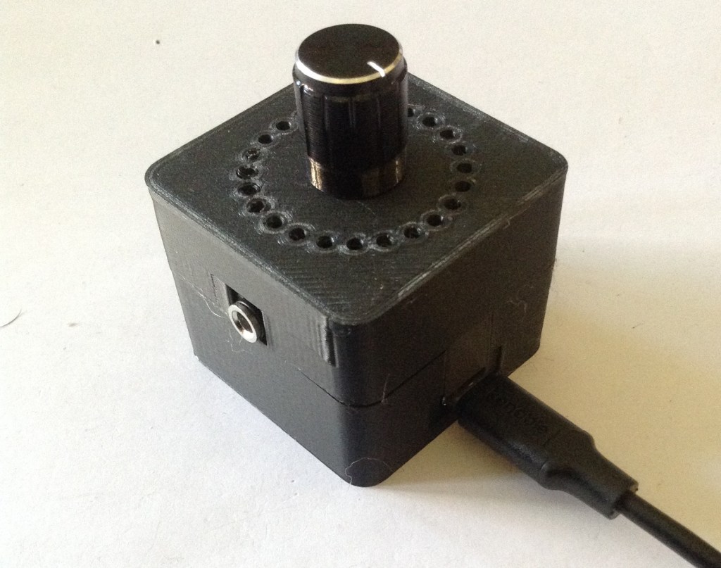
This is a simple 3D printed case for my Duppa I2C MIDI Controller PCB.
Warning! I strongly recommend using old or second hand equipment for your experiments. I am not responsible for any damage to expensive instruments!
If you are new to microcontrollers, see the Getting Started pages.
Parts list
- Duppa I2C MIDI Controller
- USB-C lead or serial MIDI.
- MIDI device
OpenSCAD Design
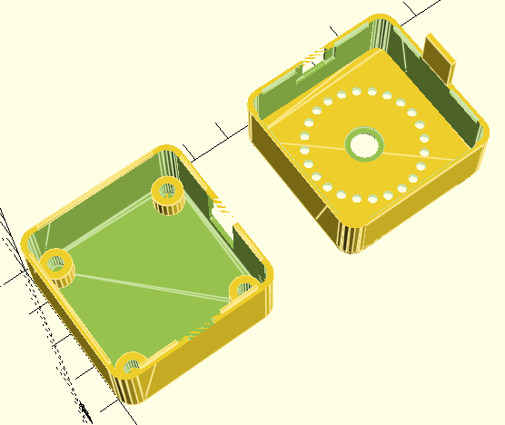
This uses some of the techniques from my Raspberry Pi 2,3,4 A+/B+ Synth Cases to define a basic box, then some cut-outs, and then to split the box and add some overlapping “lips” for a snap-fit.
There a number of functions to achieve this, but some of them are just collecting together the others in the right sequence.
- rounded – a basic “rounded” box module.
- standoff – the PCB supports.
- build_lips/build_lip – as expected, creates the overlapping lips. There is a parameter (solid) which determines if the lip is added to or subtracted from the case.
- base – the main box shape, less the actual top.
- top – the top plate that includes holes for the potentiometer and the LED ring.
- box – uses base() and top() to build a complete box.
- box_base/box_top – uses box and an intersection to produce the two halves of the main box.
At the top level box_base, box_top and standoff (four times) actually builds the complete case.
In terms of assumptions about the build:
- Most importantly, this assumes the use of PH5.0 headers to mount the Waveshare Zero device.
- It also assumes the use of a serial MIDI TRS socket.
- It should allow for M3 spaces and is build to assume two sets of 10mm spacers as described in the Build Guide.
Notes on printing:
- I found getting adhesion for the top with all those circular holes quite a challenge. In the end I increased the bed temperature and slowed the print right down to around 40% for the first layer and that seemed to improve thing quite a bit.
- Once complete I had to tidy up the LED holes a little by hand with a 2.5mm drill bit.
- The additional tag above the USB socket is quite delicate, so care is needed when snapping the case together.
Errata/Improvements:
- For my own build, the potentiometer shaft doesn’t stick out as much as I’d like. It is hard to find a knob that doesn’t have to be altered to fit and stay in place.
- I did wonder about using a thinner layer of 3D print over the LEDs rather than complete holes. I might still try that as an option to see how it works.
Closing Thoughts
This is a little tall, but I’m not sure what, in reality I could do about that. There might be some option for shrinking it a little, especially if the Waveshare Zero RP2040 is soldered directly to the PCB. But it would only save, maybe up to 6 mm in height, so it is probably not worth the effort.
But apart from that, this seems to have come out really well. The holes the LEDs I thought were perhaps a bit of a compromise, but actually they seem to work fine.
Kevin