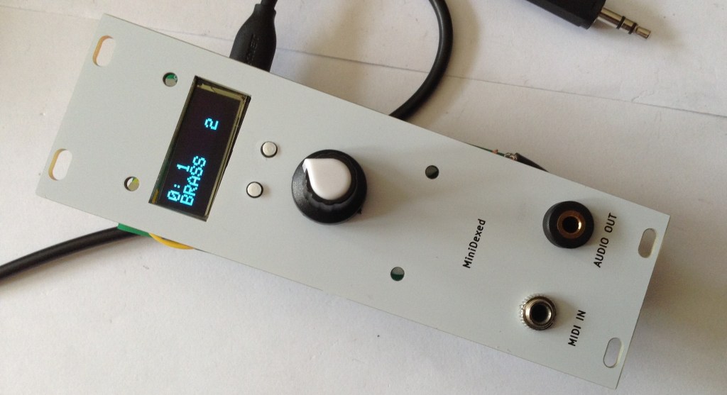
Now that I have a picoDexed with a display an encoder it is very tempting to create a version of my MiniDexed EuroRack PCB for it.
But as a short diversion, there is another possibility – can I use a RP2040 that is already in a Pi Zero form factor with my existing MiniDexed EuroRack PCB Design?
Spoilers: The answer, it turns out, is no. Something is not quite letting this work for me – it’s close, but I’m just not there yet. Here is another attempt where it works: picoDexed + MiniDexed EuroRack.
Warning! I strongly recommend using old or second hand equipment for your experiments. I am not responsible for any damage to expensive instruments!
If you are new to microcontrollers and single board computers, see the Getting Started pages.
Pi Zero RP2040s
I’m aware of a couple of products that were available to put a RP2040 into a Raspberry Pi Zero form factor:
- Red Robots Pico to Zero adaptor.
- Stacky-Pi by SB Components.
- Waveshare RP2040 PiZero.
- Pico to Pi HAT.
- Update: I’ve just found the following open source design: https://github.com/bablokb/pcb-pico-pi-base – details of how I’ve used this can be found here: picoDexed + MiniDexed EuroRack
The first two were available on Tindie and other places, and as far as I can see, both appear to use the same mapping of RP2040 GPIO to RPi 40-pin header. The Red Robot board doesn’t seem to be available anymore, and whilst there are a few Stacky-Pis on Tindie, in most places it seems to be discontinued.
I don’t know anything about the Waveshare or Pico to Pi, but might grab myself one of each.
I’ll give the open source design a try (and possibly save me designing my own…).
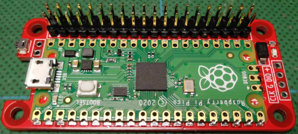
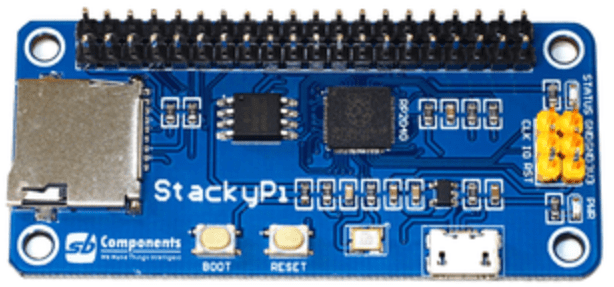
As can be seen above, the Red Robots board is designed to take an actual Pico, whereas the Stacky-Pi is its own board with an on-board RP2040.
Mapping over to MiniDexed/RPi Zero
The following table lists the RPi GPIO connections I used in my MiniDexed board and how they map onto the RP2040 using the above boards.
| RP2040 | Use | RPi | Rpi | Use | RP2040 |
| 3V3 | 5V | ||||
| GP20 | LCD SDA | GP2 SDA | 5V | ||
| GP21 | LCD SCL | GP3 SCL | GND | ||
| GP4 | GP14 TXD | GP0 | |||
| GND | GP15 RXD | MIDI IN | GP1 | ||
| GP17 | GP18 | I2S BCLK | GP28 | ||
| GP27 | GND | ||||
| GP22 | GP23 | ||||
| 3V3 | GP24 | ||||
| GP3 | RE B | GP10 MOSI | GND | ||
| GP4 | RE A | GP9 MISO | GP25 | ||
| GP2 | RE SW | GP11 SCLK | GP8 | ||
| GND | GP7 | ||||
| ID_SD | ID_SC | ||||
| GP10 | SW BACK | GP5 | GND | ||
| GP11 | SW HOME | GP6 | GP12 | ||
| GP12 | GP13 | GND | |||
| GP13 | I2S LCLK | GP19 | GP16 | ||
| GP26 | GP20 | ||||
| GND | GP21 | I2S DATA | GP15 |
The two key problem areas will be the I2S interface and encoder, which both require consecutive GPIO pins for the PIO code to do its magic.
The encoder should be fine – pins RE A and RE B map onto the Pico’s GP3 and 4.
The I2S interface is going to be tricky, as with a BCLK on GP28, it will be expecting LCLK on GP29 rather than the GP13 it is currently routed to on the board. Quite apart from the fact that GP29 isn’t even broken out on a Pico.
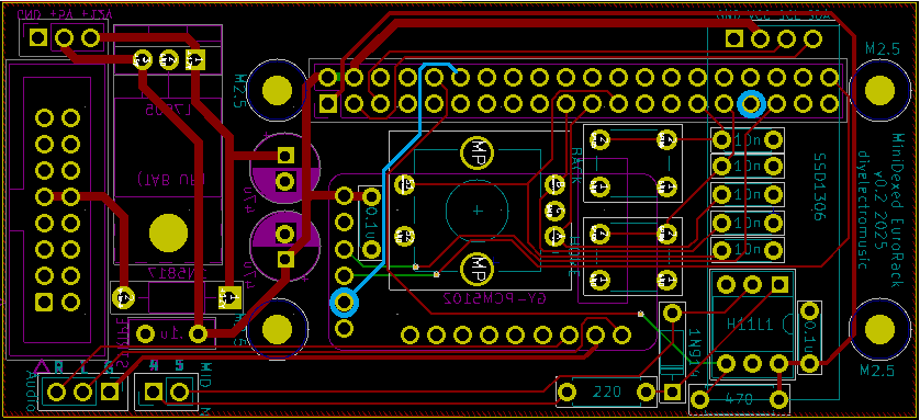
The obvious thing to explore is if the BCLK connection can be routed through to GP13 on the RPi header, or GP12 for the RP2040. That would be handy if so.
Connecting into GP13 should be possible as this pin is currently unconnected on the MiniDexed PCB. It will involve cutting a track however for GP18. The existing track and its new destination is highlighted below in blue.
Changing I2C Bus and UARTs
There is one other complication however. The picoDexed configuration has the ssd1306 connected to GP2 and GP3 which are multiplexed onto the I2C bus 1.
The adaptor configuration maps SDA/SCL onto GP20/21 which are multiplexed onto I2C bus 0. I updated the code to support changing I2C bus in addition to changing IO pins. Arguably, I should probably have supported this in the first place anyway…
A similar issue exists for the UART, but unfortunately that isn’t quite so easy to change.
I can take a similar approach to the above for the Serial MIDI link – allowing it to use either UART0 or UART1.
But that has to be matched with a change in the debug serial port too. But unfortunately, as far as I can see, that has to be configured in the master CMakeLists.txt file (as I talked about in Part 3).
New picoDexed GPIO Configuration
Given the above, the following new GPIO pins should be defined in config.h:
#define PWM_PIN         10

#define I2S_DATA_PIN    15
#define I2S_BCLK_PIN    12
#define I2S_LRCLK_PIN   13  // Implied by BCLK=12

#define MIDI_UART       0
#define MIDI_TX_PIN     0   // Not used
#define MIDI_RX_PIN     1

#define DEBUG_UART_TX_PIN  8
#define DEBUG_UART_RX_PIN  9

#define DISPLAY_I2C_BUS  0
#define DISPLAY_I2C_SDA  20
#define DISPLAY_I2C_SCL  21
#define DISPLAY_I2C_ADDR 0x3C
#define DISPLAY_W 128
#define DISPLAY_H 32

#define ENCODER_A_PIN  3
#define ENCODER_B_PIN  4 // Not used
#define ENCODER_SW_PIN 2 // Not used
In addition to this, to keep using the debug output requires the following lines adding to ‘target_compile_definitions’ in CMakeLists.txt.
    PICO_DEFAULT_UART=1
    PICO_DEFAULT_UART_TX_PIN=8
    PICO_DEFAULT_UART_RX_PIN=9
Bringing it all together…
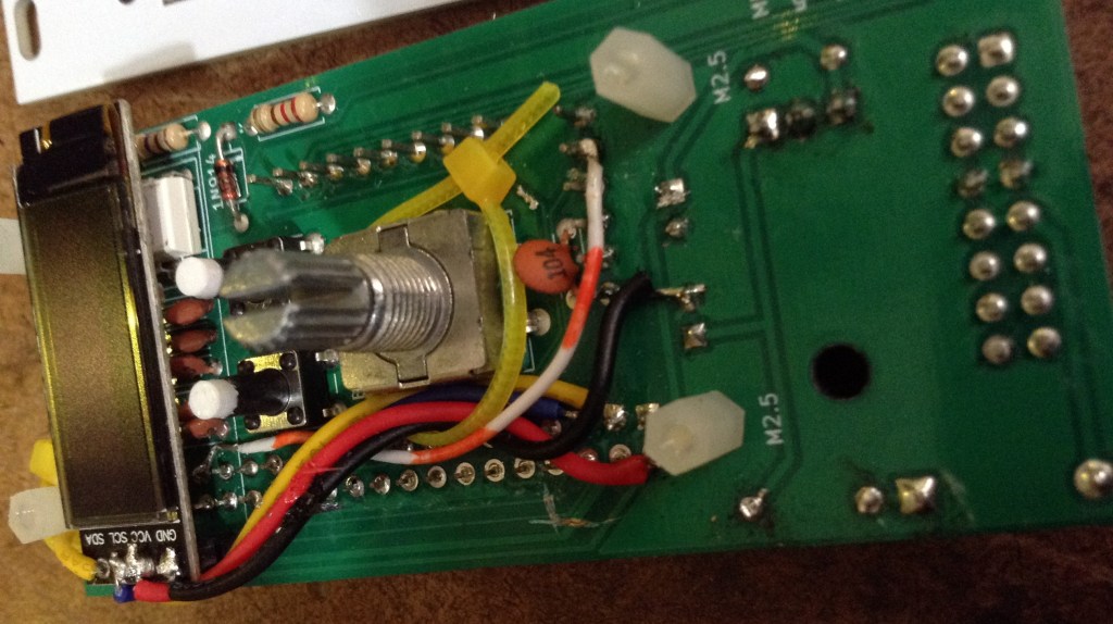
I decided to hack on my (already pretty hacked) prototype MiniDexed EuroRack board and cut and patch the trace to the DAC as described above.
The complication being the GPIO header pin I need to get to is under the OLED display, but I could just about do it – see below.
It doesn’t work. Unfortunately.
First of, I have to say, I’ve not found the Stacky-Pi particularly reliable. It took me ages to get it to successfully boot up into accepting a uf2 file, and once installed, I was struggling to get it to reliably boot and run.
Weirdly it seems to work best when I have a finger on the flash chip which seems to imply some board layout/grounding/stability issues to me… ![]()
From what I can see, the display, MIDI, serial debug and encoder are working fine though once it does get up and running.
But I just can’t get any reliable sound out of the thing at all. I managed sound once, but that was it. It is all quiet unreliable for me – far too unreliable to be useful.
Shame, as it actually looks really cool!
Closing Thoughts
It has been a frustrating afternoon. I’m having to leave this one here for now as there are just too many unknowns at the moment to really get to the bottom of what is going on.
I thought the Stacky-Pi would be a quick and easy fix, but haven’t ever used them before, and the fact that they are discontinued and there is very little information that I can find online about them makes me think perhaps they aren’t worth persevering with.
So I have a number of options now:
- Try a Waveshare RP2040 PiZero. As there are a lot more peripherals, I’m not sure how much what I’m doing will translate across, to be honest, it cost wise, it’s essentially the same as a Zero itself, which I know “just works”.
- Do I design my own Pico to RPI GPIO converter board to let me use that with my existing MiniDexed EuroRack design? Tempting and probably not that hard.
- Update: I’ve since found (and ordered) https://github.com/bablokb/pcb-pico-pi-base
- Update 2: And it works! picoDexed + MiniDexed EuroRack
- Update: I’ve since found (and ordered) https://github.com/bablokb/pcb-pico-pi-base
- Do I attempt to do something with the Pico version of my EuroRack 6HP MCU Experimenter Module? Sounds initially easy but I suspect forcing a MiniDexed into this module eventually will hit other at the moment unforeseen issues.
- Or do I just go for it and put together a special picoDexed EuroRack module itself.
I might have one more go with the Stacky-Pi. I haven’t quite given up. I’ll have to do some research – maybe sprinkling a few capacitors around the board or some updated GND connections might help. Answers on a postcard (or in the comments) if you have any ideas.
I’ll get a Waveshare RP2040 PiZero on order, as I’ve had quite a bit of success with their own “Zero” miniature boards so far, and now I’d like it know if it would work 🙂
To be continued…
Kevin
