Having recently acquired a Daisy Seed to play with, it seemed natural to produce an MCU board for use with my EuroRack 6HP MCU Experimenter Module.
Warning! I strongly recommend using old or second hand equipment for your experiments. I am not responsible for any damage to expensive instruments!
If you are new to electronics, see the Getting Started pages.
The Circuit
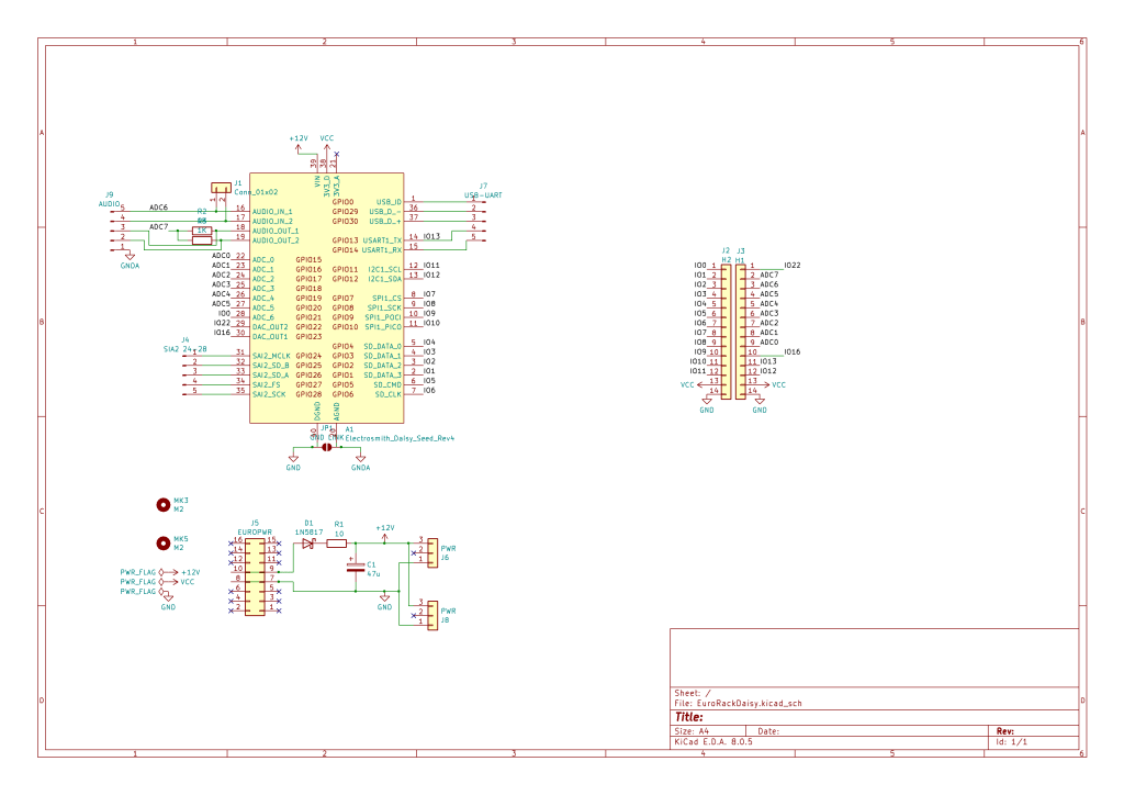
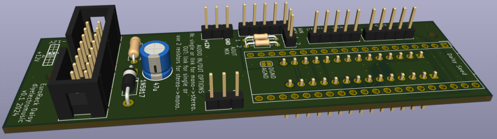
This is essentially just a breakout for the Daisy Seed with a EuroRack compatible power supply and connector that is compatible with my EuroRack 6HP MCU Experimenter Module.
There are a few points to note with the circuit however:
- I’ve kept analog and digital GND separate but linkable via a solder jumper.
- I’ve only broken out a single audio input and output channel to the connector, and have used the pins labelled ADC6 and ADC7.
- I’ve included the option to have both audio inputs on the Daisy (left and right) from the same source (via ADC6).
- I’ve included an option for a simple passive mixer for both audio outputs to the same output (via ADC7).
- I’ve included additional header pins to breakout some of the Daisy Seed IO that didn’t make it to the connector: USB, UART1, and SAI2.
- I’ve also included an audio breakout header for stereo input and output if that is preferred rather than sending to the IO module via ADC6 and ADC7.
- The Daisy Seed is powered by connecting the EuroRack +12V to VIN. The DaisySeed datasheet states a VIN range of +5V to +17V.
As with the core module, these boards are meant for DIY systems only. They should NOT be used with expensive EuroRack modules, racks, or power supplies.
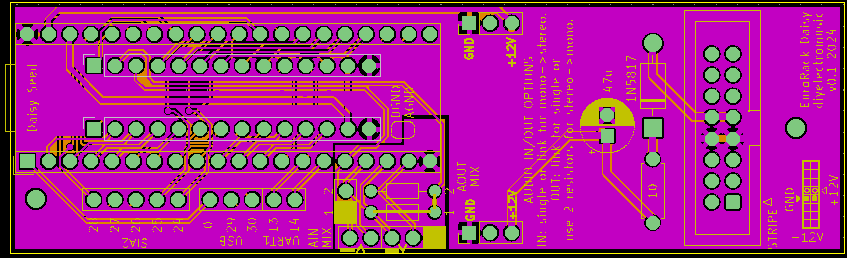
PCB Design
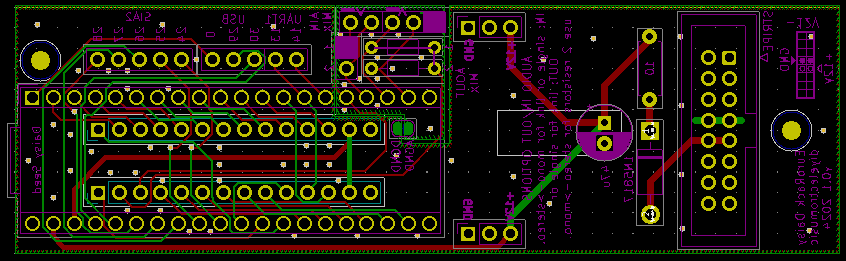
There isn’t a lot to say about this PCB. Some key points for the design:
- It supports a 16-pin EuroRack power connector but uses the same protection methods as described in the original EuroRack 6HP MCU Experimenter Module design (and with the same proviso – it is for DIY use only).
- I’ve include +12V/GND additional breakout headers in case that is useful.
- As already mentioned some of the additional IO pins are broken out to additional headers.
- As already mentioned, where there are configuration choices for the audio, 2.54mm pitch header footprints have been used to allow the use of header pins and jumpers or a 2.54mm pitch switch.
- I’ve kept the audio/analog ground section separate, but also allowed for it to be solder-jumpered to the digital ground too. This is required if the audio is routed to the IO module, but isn’t required if the additional audio header breakouts are used.
I’ve not found anything in the specification about power usage, but I did note that an official EuroRack module using the DaisySeed suggests a typical current usage of <100mA.
Using a 10Ω resistor means that there will be a voltage drop of around 10*0.100 or 1V. This gives rise to around 0.1W power to dissipate through the resistor which should be fine I believe.
But if preferred, the resistor can be omitted and replaced with a wire link.
Closing Thoughts
This was an obvious step to take and hopefully will make experimenting with the Daisy Seed a little easier for me.
Kevin
