I want to revisit my Forbidden Planet “Krell” Display looking at an alternative way to do the electronics. In particular, I’m looking at how I might embed a microcontroller in each display.
This post is a short diversion into the world of some Waveshare “Zero” format devices and a bit of background on driving programmable LEDs…
Warning! I strongly recommend using old or second hand equipment for your experiments. I am not responsible for any damage to expensive instruments!
If you are new to microcontrollers, see the Getting Started pages.
Background
I’ve recently stumbled across Waveshare’s “zero” series of microcontrollers. The ones I’ve been looking at are the:
The last of which has a fair bit in common with Pimoroni’s Tiny RP2040, which I also have.
These all partly share common pinout, in that the power, GND and UART pins are all essentially in the same place. There is a little variation – the RP2040 has an extra row of pins along the bottom, and the Pimoroni has one less pin each side and one of them is an extra GND. But apart from that, it should be possible to essentially work with any of them and just change the IO numbering.
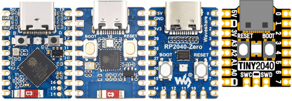
In these boards, the left hand set of headers always starts 5V, GND, 3V3 and the right hand set of headers always starts TX, RX. There are also at least four analog pins in the same place – those as indicated on the Tiny2040. Recall that the RP2040 only has four analog pins available. The two ESP32 boards actually have an analog facility on almost every pin of course.
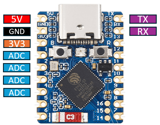
It is worth a quick note to contrast this with the XIAO, QT-Py, and similar boards, that have 5V, GND, 3V3 on the right, and TX/RX at the bottom.
The S3 also has some additional pads front and rear to break out additional IO, and as already mentioned the RP2040 has an addition row of pins at the bottom plus additional pads on the rear too.
Whilst RX/TX are always in the same place in terms of physical layout, the GPIO mapped onto them changes with the boards as follows:
| RX | TX | |
| RP2040 | GP1 / UART 0 | GP0 / UART 0 |
| ESP32-S3 | GP44 / UART 0 | GP43 / UART 0 |
| ESP32-C3 | GP20 / UART 0 | GP21 / UART 0 |
| tiny2040 | GP1 / UART 0 | GP0 / UART 0 |
Whilst all boards have castellated edges, it is worth noting that both the RP2040 Zero and Tiny 2040 actually have the RP2040 itself and some other components on the underside of the PCB, so it isn’t possible to mount this directly using the castellations (although I guess one could get fancy with cutouts…).
All four boards include a USB-C connection and BOOT and RESET buttons along with a full colour LED. The Zeros include a WS2812b off a single GPIO, whereas the Tiny2040 has a directly accessible RGB using three GPIO pins.
The two ESP32 boards, as one might expect, also include a chip antenna for the wireless support.
In each case 5V is the USB bus power and 3V3 is from the onboard regulator. All boards could be powered directly via the 5V pin, providing that USB isn’t connected at the same time.
Some of the boards would actually accept a wider input voltage range on 5V, depending on the specification of the regulator used:
- Tiny2040: NCP115AMX33OTCG – input range 1.7V-5.5V – board recommended: 3-5.5V
- RP2040 Zero: ME6217C33M5G – input range 2V-6.5V – board recommended 3.7V-6V
- ESP32C3 Zero: ME6217C33M5G – input range 2V-6.5V – board recommended 3.7V-6V
- ESP32S3 Zero: ME6217C33M5G – input range 2V-6.5V – board recommended 3.7V-6V
Note: the schematic for the RP2040 Zero shows the regulator as the RT9013-33 which has an input range 2.2V-5.5V, but the specification pages state the use of the ME6217C33.
Summarising the general stats:
| ESP32-S3 Zero | ESP32-C3 Zero | RP2040 Zero | Tiny2040 |
| Xtensa 32-bit LX7 | 32-bit RISK-V | ARM Cortex M0+ | ARM Cortex M0+ |
| Dual core | Single core | Dual core | Dual core |
| 240MHz | 160MHz | 133MHz | 133MHz |
| 512KB / 4MB / 2MB | 400KB / 4MB Flash | 264KB / 2MB Flash | 264KB / 2MB or 8MB |
But the key thing of interest for me is that as well as being pretty cheap, then are small. Each board is no more than 24x18mm in size, which makes them all an ideal candidate for embedding in something.
In my case, I’m after something to go in my Forbidden Planet “Krell” Display.
Driving Neopixels
One thing I was keen to be able to do, given these boards and their software support, was to be able to use Circuitpython and benefit from the wide range of libraries available.
One of those is the neopixel library for driving programmable LEDs such as those based on the WS2812b or APA10x and so on.
I recalled hearing that one of the first uses for the RP2040 PIO subsystem was in driving neopixels, so did some looking around. Eventually I found the following resources:
- WS2811/WS2812/WS2812B/APA104/APA106/SK6812 LED String/Strips
- Circuitpython Neopixel Essentials
- Using PIO to drive a Neopixel
- Adafruit Neopxl8 Library
The latter looked especially interesting as it appeared to be an official Adafruit library for driving Neopixels on an RP2040 using the PIO. Unfortunately what wasn’t immediately obvious to me was that this library is meant for driving 8 LED strands using consecutive GPIO pins, so I wasted a bit of time trying to work out quite what was going on.
It was particularly confusing as the library seemed to work ok with genuine WS2812b programmable LEDs, but I was wanting to use APA106 through-hole, individual, programmable LEDs and they didn’t seem to be working properly.
I found the code in the “using PIO to drive a Neopixel” post worked well on both types, so knew I must have been getting the basics right.
Eventually I just loaded up the highest level Neopixel library from Adafruit and used that. That all worked fine. I’m still not entirely sure why searching led me to the pxl8 library rather than the genuine one. No matter.
(What I’m still not clear on though, is does the Neopixel library use PIO on a RP2040 or not? This file implies support is there, but I don’t know how PIO and state machines are managed in a Circuitpython application – what if you’re using PIO for something else when you want to use the Neopixel library on a RP2040? More research is required…)
In terms of the two types – the APA106 is essentially a WS2812b compatible LED – the only difference being that the timings are slightly different. Otherwise, they both run at 800kHz and require three bytes per LED – one each for the red, green, and blue intensities of each LED. And when chained, they all act in a similar way to a shift register – that is they consume three bytes of information themselves, and then pass anything else on.
This way successive LEDs can be chained with the IN of one being connected to the OUT of the previous one.
Note: some LEDs have a different order, and some include a fourth byte for W(hite). So there are RGB, GRB, RGBW, and GRBW variants. Some also run at 400kHz. The library usually allows for alternative configurations where necessary, although I’ve not managed to find out if 400kHz strips are supported.
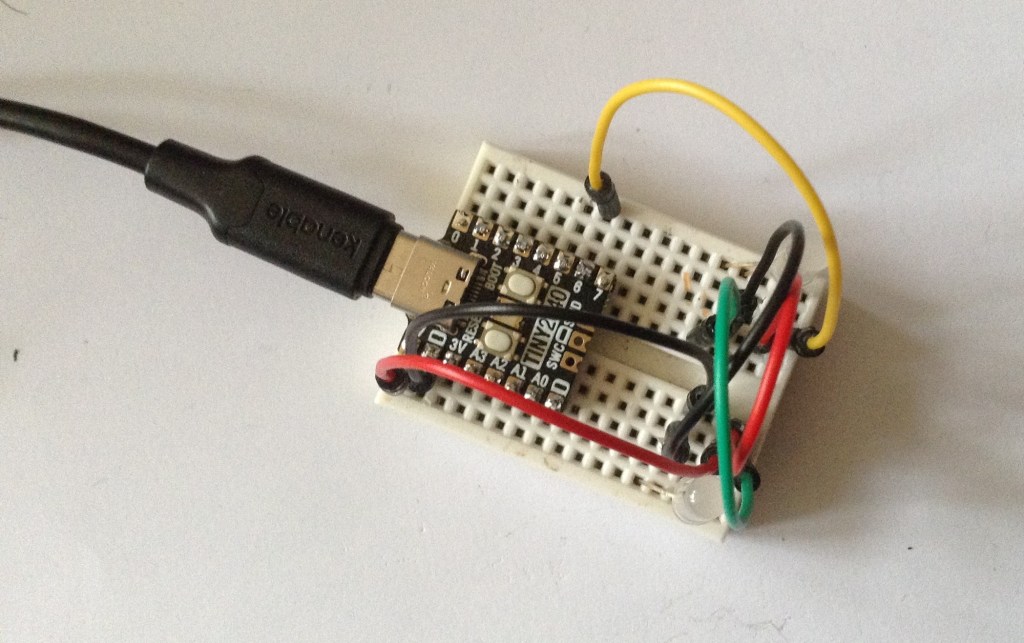
The code to drive two of my APA106 neopixel-a-likes from GPIO 6 is:
import time
import board
import neopixel

pixels = neopixel.NeoPixel(board.GP6, 2, brightness=0.3, auto_write=False, pixel_order=neopixel.RGB)

while True:
    pixels.fill((255,0,0))
    pixels.show()
    time.sleep(1)
    pixels.fill((0,255,0))
    pixels.show()
    time.sleep(1)
    pixels.fill((0,0,255))
    pixels.show()
    time.sleep(1)
This requires the following libraries to be installed from the Circuitpython Library Bundle:
/lib/neopixel.mpy
/lib/adafruit_pixelbuf.mpy
Neopixels, WS2812b, APA106…
Neopixel is the name given to programmable LEDs by Adafruit. In practice they tend to be based on the WS2812b driver chip. Well actually, WS2811 is the stand-alone chip, but when embedded with a RGB LED in a 5050 (5mm square) surface mount package, it will make a WS2812b LED.
The APA10x series are all (I believe) WS2812b compatible and the APA106 is a through-hole, single programmable LED. But there are two variants with slightly different pinout configurations as follows:
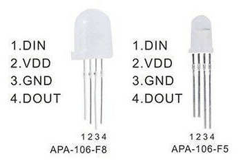
Generally speaking it would appear that the 8mm variant (APA-106-F8) has the pin arrangement on the left, and the 5mm variant (APA-106-F5) has the pin arrangement on the right. This certainly seems to be the case for me.
Comparing the datasheets for the WS2812b and APA106, we can see that the timings for the protocol are slightly different, but not by much. The general idea is that the overall space for a single bit has a defined time, but a 1 has a different proportion of that time high compared to a 0. Then at the end of the bitstream there will be a short reset period which signifies the end of the data.
The canonical references for driving Neopixels are:
- The Adafruit Neopixel Uberguide – as it says, pretty much everything you need to know about Neopixels.
- Neopixels revealed – far more than you probably ever wanted to know about driving Neopixels.
- WS2812b and APA106 datasheets.
Closing Thoughts
I’ll leave this post here for now. I’ve now managed to drive my APA106 through-hole LEDs successfully from a TinyRP2040 device, so I’m happy I’ve covered the basics and can move forward.
Some interesting variations of these kinds of boards are:
- Waveshare RP2040 Matrix MIDI Monitor – essentially the same as the RP2040 board with wih a built-in LED matrix on the top.
- ESP32C3 OLED Mini MIDI Montor – an ESPC3 in a similar format with a built-in OLED display. Although note that the pinout of this one is slightly different and the pins are 1 “step” further apart!
Kevin
