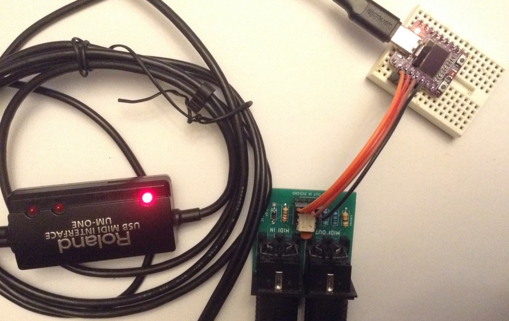
I’ve picked up a couple of really neat, small, ESP32C3 based boards with a built-in 0.42″ OLED display and so whilst wondering what to do with them, I thought a small MIDI note monitor might be a bit of fun.
Warning! I strongly recommend using old or second hand equipment for your experiments. I am not responsible for any damage to expensive instruments!
These are the key tutorials for the main concepts used in this project:
- Arduino MIDI Library
- ESP32 Arduino Getting Started
- U8G2 Graphics Library
- ESP32-C3 0.42 OLED usage notes
If you are new to Arduino, see the Getting Started pages.
Parts list
- ESP32C3 0.42 OLED
- 3V3 MIDI interface (more here)
- Breadboard and jumper wires
The Circuit
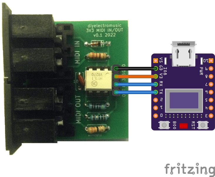
This is using my 3V3 MIDI Module PCB connected as follows:
- GND – GND
- 3V3 – V3
- IN – RX
- OUT – TX
The Code
We know from this post that the UART comes up as Serial0 in the Arduino environment, as USB is mapped to two dedicated pins on the ESP32C3.
But the default MIDI constructor for the Arduino MIDI Library for ESP32 doesn’t seem to work, so I’ve had to declare it explicitly as follows:
MIDI_CREATE_INSTANCE(HardwareSerial, Serial0, MIDI);
The same post also describes the use of the U8G2 graphics library which can be installed via the Arduino Library manager.
The code is split into various sections to manage the graphics display, the MIDI, and the general Arduino code.
I wanted a blocky-note display, a little like the one I did here: TFT MIDI Display – Part 3, but in this case the display is monochrome only. And quite a bit smaller of course.
The key element is getting everything scaled to fit on the display. I have 40×72 pixels to play with, which isn’t a lot, and ideally a full range of 128 MIDI notes to display.
To get 12 notes on a row, means 6 pixels per note block. If I go with 4 pixels vertically too, then that would give me 10 rows making 120 MIDI notes in total. That is close enough!
I’m using 5×3 blocks to leave a pixel gap between blocks.
Calculating the (x,y) coordinates for each block from a MIDI note thus becomes
x = 6 * (n % 12);
y = 4 * (n / 12);
There is some messing around to do with the fact that y=0 is at the top of the display, and also that the default orientation of the display is “USB port at the bottom” – I’d rather the USB port was at the top, but this is a simple matter of calculating the right offsets and matching to the rotation specified in the code.
I didn’t sit and work it out in theory – I just tried some offsets until the right values had the right signs and so on. I included a test mode that just sits and draws all the boxes and then removes them again.
In terms of scheduling the MIDI and display updates, I’ve adopted the following principles:
- MIDI is scanned every time through the loop.
- Graphics are written out to the display only if something has changed, and I only check for a change once every 32 scans.
- As the graphics library is frame-buffered, I can update each MIDI note block “live” on reception of a MIDI NoteOn or NoteOff, but it will only show on the next scan of the graphics.
This seems to give me a useful balance of MIDI responsiveness and graphical updates.
I’ve enabled MIDI THRU so that the board can be put in series in a MIDI link.
Closing Thoughts
I really like these displays. You can’t really appreciate the scale until you stop and look at the size of those mini solderless breadboards it is plugged into. The board itself is barely the size of a MIDI DIN plug.
Completely impractical of course, but still a lot of fun. And the Lo-Fi Orchestra – Mercury from The Planets, with all that jumping around and chromatic runs, is quite fun to watch going through it.
Kevin
