In the first part I described the concept and basic design parameters I was looking for and then in Part 2 I looked at the detailed electronic design, and in Part 3 at the code, for a board based on the ESP32 WROOM module I have. In this part I look into some additional mechanical assembly options to attempt to “finish it off” in a useful way.
- Part 1 – This introduction and high-level design principles.
- Part 2 – Detailed design of an ESP32 based PCB.
- Part 3 – Software design.
- Part 4 – Mechanical assembly and final use.
- Part 5 – Six simple experiments to try.
Optional additional things to try:
- Part 6 – Testing it out with other synth kits.
- Part 7 – Integrating it with my Raspberry Pi Pico MIDI Touch Keyboard.

Warning! I strongly recommend using old or second hand equipment for your experiments. I am not responsible for any damage to expensive instruments!
Additional Connector Breakout Panel
As I mentioned previously, the main board has header pins for the following connections:
- Power and power switch.
- Audio output.
- MIDI IN.
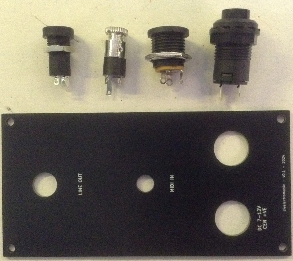
To break these out in a useful way, I’ve designed a 50x100mm panel that can be used to provide the following:
- 2.1mm barrel jack socket for 7-12V DC input.
- Click-toggle switch for power on/off.
- 3.5mm TRS stereo audio output.
- 3.5mm TRS “type A” MIDI IN.
Update: Note there is an alternative connector panel design too that can be used with my –Raspberry Pi Pico MIDI Touch Keyboard. For details, see Part 7 of this series.
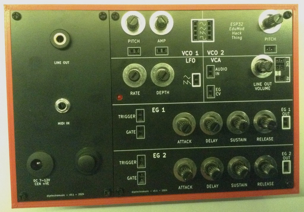
I’ve put together the following panel using KiCad and had it made as a PCB with black solder mask and white silkscreen.
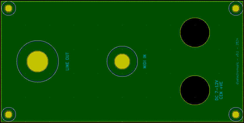
The Line Out hole is M8 8.4mm mounting hole, edited to remove the pad. The MIDI IN is a 6mm mounting hole. The two cutouts for the power switch and barrel jack socket are 12mm diameter holes and the mounting holes are the same as those used for my panel design: M2.5 holes positioned 3.0mm in from the edges.
In case you’re wondering, these are the same connections I’ve used on all my previous panel projects (for MiniDexed, Zynthian or my CD Rack Synth).
Unfortunately when it came to it, my hole for the power switch should have been 12.5mm not 12.0mm so I had to slightly widen it with a drill bit. I spotted this with my Zynthian panel and then promptly forgot about it. Oh well.
In any case, the final dimensions o course will all depend on the connectors used – these are mine.
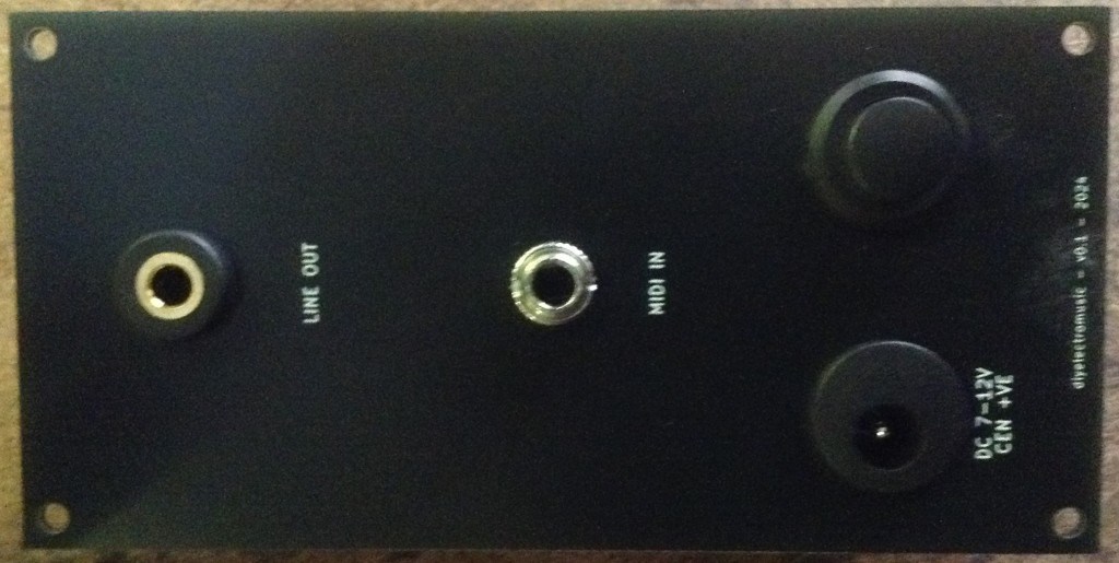
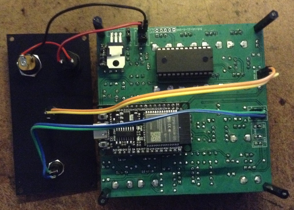
With the connectors assembled:
The following illustrates the wiring to the connectors from the main PCB for the connectors I’m using.
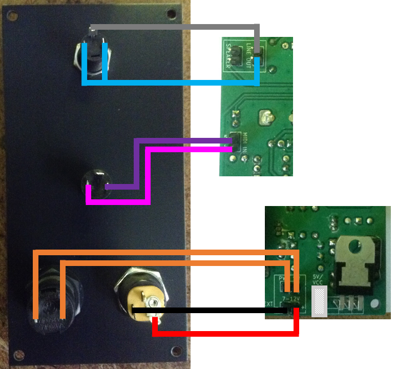
Notes:
- The audio out socket is a stereo socket, but the signal from the PCB is mono, so needs connecting to both terminals.
- The MIDI socket doesn’t have GND connected, as is usual with MIDI IN sockets. Tip is pin 5 and Ring is pin 4 for a “type A” MIDI TRS socket (the adopted MIDI standard wiring for TRS sockets).
- Be sure to connect the positive power pin correctly. I’ve connected it to the pin of the barrel jack to use with a “centre-positive” supply.
- I’m not using the switched connector for the barrel jack socket.
A jumper is required for the 5V/VCC header pins to attach VCC to the output of the regulator. WARNING: This jumper should be removed if the ESP32 module is ever powered up via USB.
As an alternative, it is also possible to jumper the “PWR SW” connections on the PCB and connect the barrel jack and switch directly together at the panel as shown below.
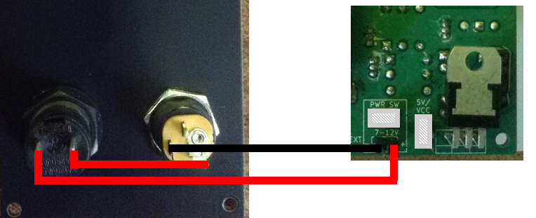
This is what I ended up doing as shown below.
Improvements and Errata:
- As already mentioned, in my case the power switch hole needed to be 12.5mm in diameter.
- The text is a little small. I should have noted what size text I’d been using on the other panel and designed this one to match. To be honest, I thought I had, but obviously not!
- It might have been nice to include a line here or there for aesthetic reasons, to match the existing panel.
- For the sockets I’m using, it can sometimes take a bit of pressure to get a MIDI jack plugged in. I really ought to have had some support being the PCB panel here to stop it flexing.
3D Printed Enclosure
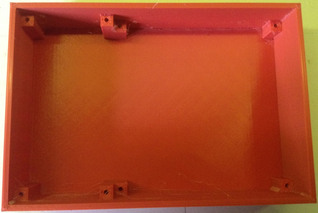
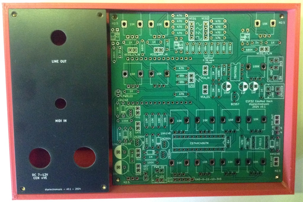
I’ve used OpenSCAD to design a box to house both the main board and the connector panel. The box is essentially 150mm x 100mm x 35mm (give or take).
I’ve had to allow for the difference in mounting depths of the PCB + panel vs just the connectors panel.
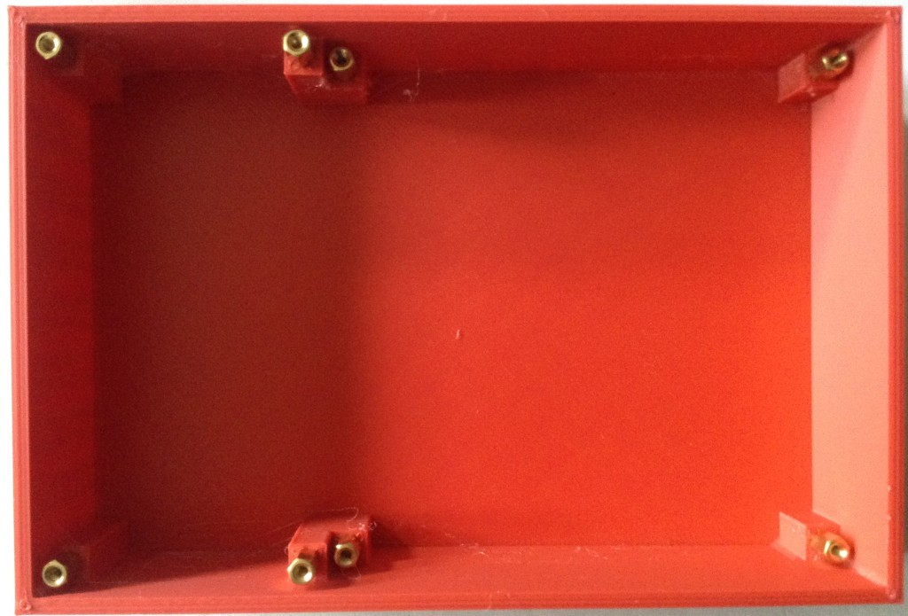
I’ve included 2.7mm diameter mounting holes in the build, which seem to quite happily take a brass M2.5 mounting spacer. To allow for other spacers/screws to screw in, I’ve allowed for 7mm spacers to sit underneath the panels/PCBs.
To get the spacings right, I used a number of test prints both for the panel dimensions and for the heights of the mounting columns.
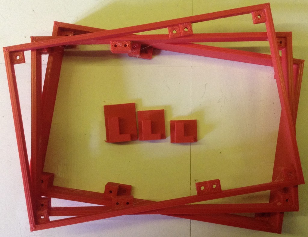
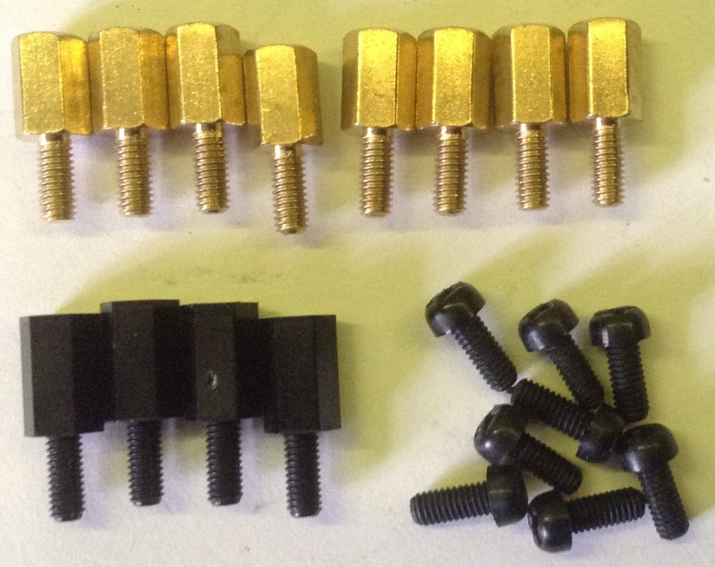
The following spacers are required:
- 8x 7mm M2.5 brass spacers with a 6mm screw.
- 4x 8mm M2.5 nylon spacers with a 6mm screw.
- 8x 6mm M2.5 nylon screws.
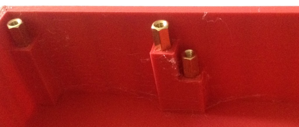
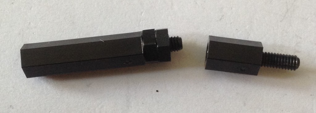
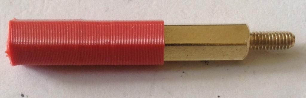
The brass spacers need to be screwed into the 2.7mm holes in the 3D printed box. I found using a longer spacer as a handle worked pretty well for screwing them in – add a couple of nuts to stop it getting screwed too tightly into the spacer. It naturally doesn’t work if you need to undo them again.
I’ve also created a simple 3D-printed tool (see the GitHub repository) that will help screw in and unscrew spacers. It is only a single line of filament thick, so won’t take a lot of pressure, so for a particularly difficult spacer then pliers are still the best bet, but it might make the others a bit quicker to get in and out.
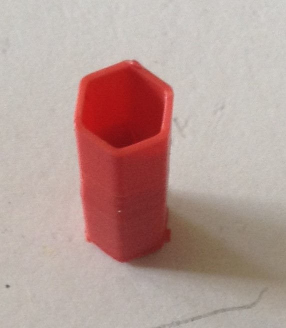
Note: some gentle pressure is required, but if they start to go in at an angle then there is the possibility of cracking the plastic mounting column, so some care is required.
My print wasn’t perfect – there was one corner of the base that didn’t seem to adhere as well as the rest, so I had to use a bit of “superglue” to stick it back together. I don’t know if that is my design or just bad luck.
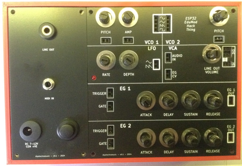
But otherwise, it seemed to print ok. Print time for me was just over 5 hours. Here are some positioning photos.
Enhancements:
- The way the screw spacers fit seems to work ok, and getting them in isn’t too much of a chore, but trying to get them out again is really quite difficult.
- It might be nice to include some means to secure a 9V battery inside, underneath the connector panel making for a completely self-contained unit. I might even be able to wire things up so that gets switched out if something is plugged into the barrel jack.
- I’ll need to see if any further prints also have a “pulling away” issue to see if the design needs tweaking some more.
- It might be nice to find a way for some kind of “quick release” mechanism to allow me to reprogram the ESP32 if required.
Closing Thoughts
The focus on this design was a relatively cheap BOM, not particularly “design for manufacture”. It was always meant to be a “build it yourself” box and from that point of view, it is quite labour intensive to build one.
But it isn’t ridiculous. I’d estimate it probably takes around 3-4 hours to put a single unit together with most of that putting together the PCB, with a 5-hour print for the enclosure. It would be less per unit if doing several at once I suspect.
My estimates for costs would be a single module costing around £50 going on a 5-unit cost for PCBs and panels, but I think you could probably make four or five for around £100 or thereabouts. I haven’t costed it all out fully and haven’t looked at how much filament is required for the box.
I still need to develop the code a little more – I’d like a more optimised reading of the analog inputs for example, and I’m not convinced I’ve got good enough logic around the MIDI handling yet, but it’s pretty close.
I think I will print a box with no back though to allow me to more easily develop and update the code on the ESP32. It isn’t easy to take them apart once put together!
So would I recommend you spend the time and money to build one (or more) yourself? No – not at the moment unless you’re happy experimenting with everything and accept it might turn out to be time and money wasted.
But this is certainly a pretty good basis on which I can continue to experiment now.
If I manage to get it working satisfactorily then I’ll have to put together some “patch cards” with some simple experiments to get things started, but for now, I think this is probably the end of this series of posts about the design and building of the box.
Kevin

One thought on “Educational DIY Synth Thing – Part 4”