This is the design for a MiniDexed IO board for the Raspberry Pi 5 that supports four GY-PCM5102 modules as described here: RPi 5 Quad Stereo Sound with PCM5102A.
- Build guide here: MiniDexed Quad DAC PCB Build Guide.
Warning! I strongly recommend using old or second hand equipment for your experiments. I am not responsible for any damage to expensive instruments!
If you are new to single board computers, see the Getting Started pages.
The Circuit
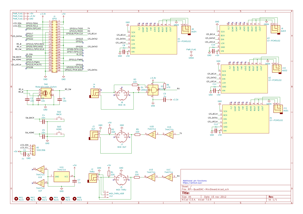
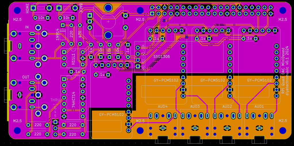
This is based on my MiniDexed Raspberry Pi IO Board including provision for a SSD1306 OLED display, two buttons, MIDI IN, OUT and optional THRU and a rotary encoder.
It includes connections for four GY-PCM5102 modules using the four I2S lanes of the Raspberry Pi 5, but note that it is not intending to use the built-in 3.5mmm stereo output of any of the PCM5102 modules but instead will hook up additional 3.5mm TRS sockets to the audio L/R/GND additional pins.
It uses the following GPIO pins:
| 3.3V | MIDI power |
| 5V | PCM5102 and SSD1306 power |
| GND | |
| GPIO 2/3 | LCD SDA/SCL |
| GPIO 9/10/11 | Rotary Encoder |
| GPIO 5/6 | Back/Home buttons |
| GPIO 18/19 | PCM5102 BCK/LCK – common |
| GPIO 21/23/25/27 | PCM5102 DIN – Modules 1-4 |
| GPIO 14/15 | TX/RX MIDI |
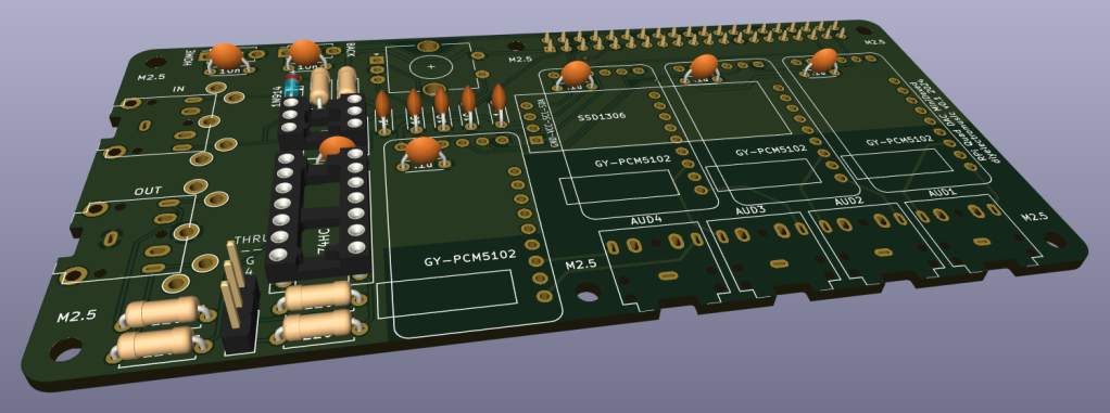
PCB Design
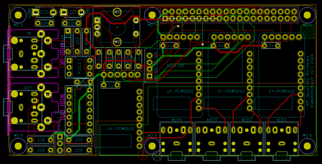
The design allows for either DIN or TRS MIDI sockets. The DIN sockets are mounted underneath the PCB whereas the TRS sockets (if used) will be on top with the other components.
The (2.5M) mounting holes align with the mounting holes on the Raspberry Pi.
The decoupling capacitors for the GY-PCM5102 modules have been positioned underneath the modules themselves. This means they can either be bent flat or soldered onto the underside of the board.
I’ve kept the analog/audio ground section distinct from the rest of the digital board. Each PCM5102 module has additional audio outputs in the additional row of pins as follows:
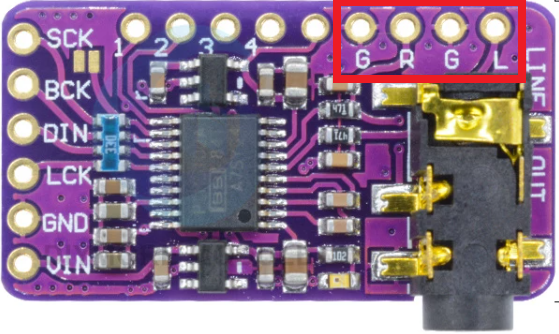
In order, these pins are GND – right – GND – left and the board routes these to the R/L channels of the associated audio out stereo TRS socket.
Note also that the SSD1306 display is positioned to sit above the PCM5102 displays and will probably need to be configured in “rotated” mode to correctly show the menus as the idea is to have all sockets at the rear of the board (so the GPIO header will actually be at the front).
MIDI THRU is left as an optional addition via the use of jumper headers.
Closing Thoughts
To be honest, I was quite surprised that all this fitted into a sensible Raspberry Pi-shaped footprint, but it does!
Kevin

thanks for this great article. Currently I’m using the DAC8x from HifiBerry. This seems to be a similar approach. I use it for initial investigations with CamillaDSP. But often I have the problem that the channels are sweept after power up. Do you have encountered the same? Best regards and many thanks.
LikeLike
I’ve not used this “in anger” yet, I was only tinkering. What do you mean by “sweept” after power up? I’ve not noticed anything particularly significant happening, but I’ve not really hooked all outputs at the same time to an external setup, so might not have noticed anything odd…
LikeLike
By “swept” I mean that CamillaDSPs mapping (for example for 4 way speaker) is not consistent. Sometimes the signal from the tweeter comes out of the subwoofer TRS for example. The problem is most likely not inside CamillaDSP, because the bar graph on the webinterface match the expectation according to the input frequency / signal.
LikeLike
I see, in that case, sorry – no, I don’t know 🙂
Kevin
LikeLike