In the first part I described the concept and basic design parameters I was looking for and then in Part 2 I looked at the detailed electronic design for a board based on the ESP32 WROOM module I have. In this part I go into detail about the code.
- Part 1 – This introduction and high-level design principles.
- Part 2 – Detailed design of an ESP32 based PCB.
- Part 3 – Software design.
- Part 4 – Mechanical assembly and final use.
- Part 5 – Six simple experiments to try.
Optional additional things to try:
- Part 6 – Testing it out with other synth kits.
- Part 7 – Integrating it with my Raspberry Pi Pico MIDI Touch Keyboard.
Warning! I strongly recommend using old or second hand equipment for your experiments. I am not responsible for any damage to expensive instruments!
The ESP32 EduMod Hacked Synth Thing
As mentioned in the last part, the principles and code I’m using are taken from these previous posts:
I also now have a built PCB design to make development and testing a lot easier.
Recall the following design choices:
- The two ESP32 DACs are the output for two envelope generators, each driven by four pots (in standard ADSR configuration), a trigger and a gate signal.
- There are ESP32 PWM outputs for two VCOs, each with four waveforms (sine, triangle, saw, square) and an analog input (pot or CV) for frequency and amplitude.
- ESP32 PWM outputs are also used for a LFO with rate and depth analog controls.
- The ESP32 UART is used for MIDI in.
- ESP32 digital IO is used for the envelope GATE and TRIGGER signals, although they are level inverted, i.e. they should be read as active LOW.
Othe points to note:
- There are three “native” analog inputs used for the two VCO pitch and amplitude CVs. All other pots are read via a CD4067 16-way multiplexer.
- Software will determine how the VCO CVs interact with the potentiometers.
- The UART RX pin will be used for MIDI and the UART TX pin will be used for one of the PWM outputs, so there will be no serial port (via USB) for diagnostic output.
- The ESP32 is a dual core microprocessor, so the aim is to split the functionality across the two cores.
High Level Design
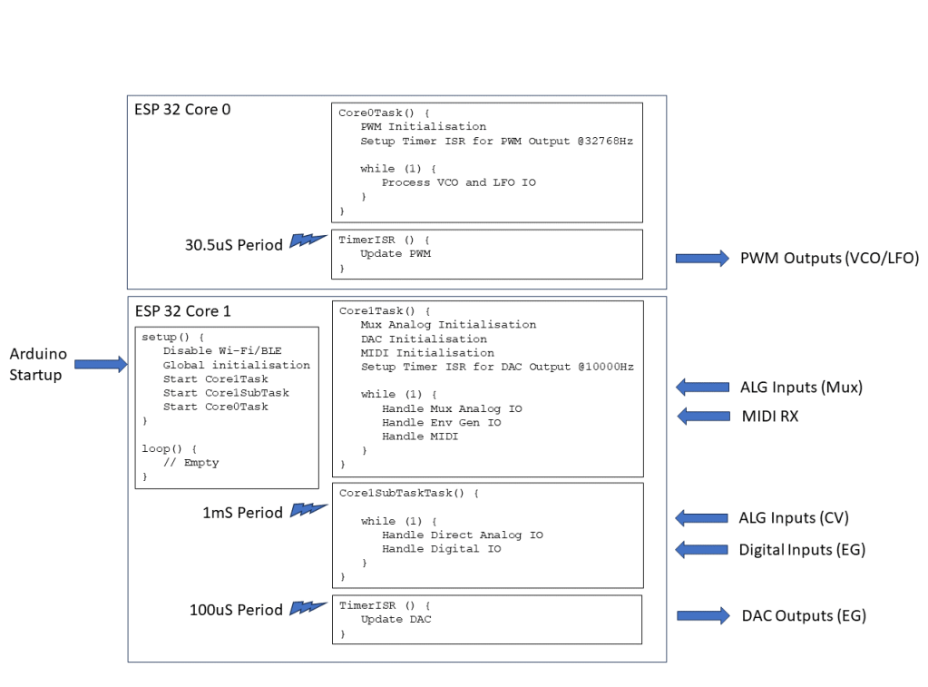
The tasks will be split as follows:
- Core 0:
- Runs the PWM timer at 32,768Hz (although the sample rate will be half this – more on that later).
- Manages the PWM outputs for the two VCOs and the LFO.
- Core 1:
- Runs the EG timer for the DAC at 10,000 Hz.
- Handles the reading of all the IO: “real” analog values and digital IO in a periodic sub-task at 1kHz
- Handles multiplexed analog values and updating envelope parameters.
- Handles MIDI.
Multicore ESP32 Arduino
Multicore support for the ESP32 on Arduino is provided using FreeRTOS tasks. For a FreeRTOS application, the default Arduino setup()/loop() will run on core 1. However, once tasks have been created to run on the second core, the default loop is no longer used (I believe).
FreeRTOS enables multitasking on a single CPU (core), each with its own internal priority relative to other tasks. But I’m only using it to start a single task on each core. This is achieved using the xTaskCreatePinnedToCore() function. The last parameter specifies which core to use and the 5th parameter indicates the priority – both are set to “1” as there is only a single task on each core.
The Arduino startup code has thus been reduced to the following:
void core0Entry (void *pvParameters);
TaskHandle_t core0Task;
void core1Entry (void *pvParameters);
TaskHandle_t core1Task;

void setup () {
  xTaskCreatePinnedToCore(core0Entry, "Core 0 Task", 4096, NULL, 1, &core0Task, 0);
  xTaskCreatePinnedToCore(core1Entry, "Core 1 Task", 2048, NULL, 1, &core1Task, 1);
}

void loop () {
  // No main loop here
}

void core0Entry (void *pvParameters) {
  Task0Setup();

  for (;;) {
    Task0Loop();
    vTaskDelay(1); // Allow FreeRTOS IDLE to maintain watchdog
  }
}

void core1Entry (void *pvParameters) {
  Task1Setup();

  for (;;) {
    Task1Loop();
    vTaskDelay(1); // Allow FreeRTOS IDLE to maintain watchdog
  }
}
I’ve simulated the setup()/loop() pattern in each of the task entry points. One thing I quickly found was that if the tasks run with no release of the processor, then FreeRTOS will fail with a watchdog error.
This is why each task includes a vTaskDelay(1) call to allow FreeRTOS to do whatever it needs to do as part of its “idle” processing.
The other thing to be careful of, which would be the same even in a single core application, is that the timers and their timer interrupt routines also allow some general processing time on each core. This will become important further in the discussion.
Task 0: PWM Generation
The essence of Task 0 is the code from ESP32 and PWM. In order to simplify things I’ve created a basic oscillator class as follows:
class COsc {
public:
  COsc ();
  ~COsc (void);

  void Setup (int pwmpin, int wave, bool lfo=false);
  void QuadSetup (int sinpin, int sawpin, int tripin, int squpin);
  void ScanPWM (void);
  void SetFreq (uint16_t freq, uint16_t vol=MAX_VOL);
  void SetMVolts (uint32_t mvolts, uint16_t vol=MAX_VOL);
}
Initially the plan was to have one instance per PWM output. The pin and required waveform is configured as part of the call to the Setup() function.
But then I decided it would be more efficient to utilise the fact that the same index and accumulator can be used to read through each of the four wavetables, so created the idea of a “quad” oscillator. This just requires the four PWM pins to be used to be specified as part of the call to QuadSetup() and eliminates several calls into the ScanPWM function for separate oscillators.
There are two ways to set the oscillator’s frequency output. One is to pass in the frequency directly, the other is to pass in a millivolt reading from a potentiometer based on a 1V/oct scaling. The “zero volts” frequency is preset to be 65.406Hz, i.e. C2.
The frequency is derived from the millivolt reading using the following:
void COsc::SetMVolts (uint32_t mvolts, uint16_t vol) {
  // Set frequency according to Volt/Oct scaling
  //   Freq = baseFreq * 2 ^ (voltage)
  //
  float freq = FREQ_0V * (powf (2.0, ((float)mvolts)/1000.0));
  int f = (int)freq;
  SetFreq(f, vol);
}
With the default settings this class can be used for both VCO and LFO, but the lowest frequency for the LFO was just 1Hz. Consequently, I’ve added the option to specify a “LFO” setting as part of the single oscillator Setup() function. If enabled, then the oscillator runs 10x slower than default. This allows for frequencies down to 0.1Hz, but does mean that the frequency or millivolt parameters are now treated as being 10 times smaller than their values would imply.
Note when MIDI is added into the mix, I just use the NoteOn message to change the base frequency used for the oscillators.
The ScanPWM() function is designed to be called from the interrupt routine running at the sample rate.
The oscillators are thus created as two Quad oscillators (one per VCO) and two single oscillators for the dual waveforms of the LFO:
#define OSC_VCO1 0
#define OSC_VCO2 1
#define OSC_LFO1 2
#define OSC_LFO2 3
#define NUM_OSC 4
COsc *pOsc[NUM_OSC];
int pwmpins[NUM_OSC][4] = {
  {17,18,5,19},
  {21,22,1,23},
  {16,0,0,0},
  {13,0,0,0}
};
int oscwaves[NUM_OSC] = {
  OSC_WAVES,  // VCO 1 (quad)
  OSC_WAVES,  // VCO 2 (quad)
  OSC_TRI,    // LFO
  OSC_SAW
};

void oscSetup() {
  for (int i=0; i<NUM_OSC; i++) {
    pOsc[i] = new COsc();
    if (oscwaves[i] == OSC_WAVES) {
      // This is a quad oscillator
      pOsc[i]->QuadSetup (pwmpins[i][0], pwmpins[i][1], pwmpins[i][2], pwmpins[i][3]);
    } else {
      // A single oscillator - these are the LFOs
      pOsc[i]->Setup (pwmpins[i][0], oscwaves[i], true);
    }
  }
}
The timer configuration for Task 0 is as follows:
#define TIMER_FREQ  10000000  // 1MHz * 10 (0.1uS)
#define TIMER_RATE  305       // 30.5 uS * 10

Task0Timer = timerBegin(TIMER_FREQ);
timerAttachInterrupt(Task0Timer, &Task0TimerIsr);
timerAlarm(Task0Timer, TIMER_RATE, true, 0);
This generates a timer interrupt running at 32,768Hz from a 10MHz timer
However, servicing 10 PWM outputs means that there is no time remaining once interrupt processing is complete for any other operations. Consequently, I set things up so that the PWM outputs are updated in two blocks of 5, meaning that the effective sample rate for PWM purposes is actually now 16,384Hz:
int toggle0;
void ARDUINO_ISR_ATTR Task0TimerIsr (void) {
  toggle0 = !toggle0;
  if (toggle0) {
    pOsc[OSC_VCO1]->ScanPWM();
    pOsc[OSC_LFO1]->ScanPWM();
  } else {
    pOsc[OSC_VCO2]->ScanPWM();
    pOsc[OSC_LFO2]->ScanPWM();
  }
}
The main Task 0 Loop just pulls in the analog IO values that have been read as part of the processing of Task 1. These values are then used to set the frequencies of each VCO and the LFO.
Task 0: VCO Control
The VCO potentiometers and CV inputs have to be combined to determine the frequency and amplitude of the PWM signal.
In terms of amplitude, I’ve chosen to use the maximum of the pot or CV input to set the amplitude of VCO 1. Note that VCO 2 has no amplitude input, although with hindsight, I could have included a pot even though I’ve run out of GPIO pins for a CV input.
This means that the pot has to be turned fully “off” for the CV to become significant.
In terms of setting the frequencies, I initially thought about some kind of frequency modulation, which would have been good for linking the two VCOs together, but then decided actually I wanted a more straight forward relationship between pot and CV to allow the use of the LFO or the EGs for pitch. The result is going for a simple summation of the two inputs which gives a 3 octave range (started at C2) for each of the CV and pot, but when combined could give up to a 6 octave spread of frequencies.
When MIDI is enabled, that will set the base frequency for the summation rather than defaulting to C2. This will set the base for both VCOs, so the pots/CVs could be used for a detuning style effect.
Note: Due to the issues with the choice of pins for the inputs, the base level of the CV input for VCO2 is floating at around 300-600mV. The default (unconnected) configuration introduces an element of detuning. If the CV inputs are not wanted, then it is recommended to connect them to GND to eliminate this effect.
The result of taking this approach, combined with the frequency of scanning the inputs, means that if one VCO is used to set the frequency for the other, then it probably won’t track the voltages accurately enough for a smooth modulation. But it does generation quite a wacky “sample and hold” style aliasing effect, which actually I quite like.
I could try to do something about that, but I think in reality this is a use-case where a purely analog VCO can be added via breadboard as part of the experimentation which can be driven from the PWM VCOs – that should enable a number of possibilities for more complex oscillator modulation.
There is also some clipping at higher LFO frequencies if used as the amplitude input. This needs to be investigated to see if that is a bug in the code or handling of the CV somehow.
It is possible that this, and the aliasing of pitch, is a consequence of the frequency of scanning the analog inputs or the speed of the analogRead() function itself – it’s pretty slow. Some investigation is required to experiment with changing the frequency of the reading or rewriting to use the ESP32 API rather than the (slower) Arduino analogRead() function (more on that later).
Task 1: IO Scanning
Originally all the IO is scanned as part of Task 1’s main processing loop. This has to cover the following:
- Real analog values from the inputs corresponding to the VCO CVs.
- Multiplexed analog values for all the pots for the VCOs, LFO and two EGs.
- Digital IO for the EG gates and triggers.
I started off reading the “real” analog IO associated with the VCOs in task 0, but found that it just wasn’t being scanned frequently enough to function in any useful manner. Also, the calls to analogRead() incur some kind of processing overhead that appears to interfere with the timing of the PWM timer interrupt, leaving “blips” in the output.
I started to think about writing a FastAnalogRead() function to use the ESP32 SDK directly rather than the Arduino analogRead() function, but before doing that moved all the IO processing over to Task 1. It turns out that this seems to work adequately so if I’ve not done that at present.
But one consequence of this chain of thought is that I now have two sets of functions performing my own analog IO reading:
- MuxAnalogRead()
- FastAnalogRead()
Which both perform in very similar ways. I’ll describe the API for MuxAnalogRead(), but the same principles were used for FastAnalogRead() too.
void MuxSetup(void);
void MuxLoop(bool bVoltageReading=false);
void MuxLoopSingle (uint8_t pot, bool bVoltageReading=false);
uint16_t MuxAnalogRead (uint8_t pot);
uint32_t MuxAnalogReadMilliVolts (uint8_t pot);
The two Loop functions are designed to perform the actual reading from the hardware. Loop will read all known values in a single scan. LoopSingle() will read a single pot.
The functions MuxAnalogRead() and MuxAnalogReadMilliVolts() are used to retrieve the previously read values.
Scanning is performed using either the standard analogRead() or the ESP32 API function analogReadMilliVolts(). This is why a bVoltageReading parameter is required as part of the two Loop functions. It would be possible to calculate one from the other for every reading, but I’ve opted not to do that in order to keep the calculations required as part of a read as minimal as possible.
This allows the scanning of the hardware to happen on one core (in Task 1 in this case) yet be read from the other (Task 0).
Digital IO processing just requires monitoring the trigger and gate inputs for a HIGH->LOW transition and call the appropriate triggerADSR() or gateADSR() functions as required, although there is a bit more logic required to work in the MIDI input.
I was finding that scanning MIDI was introducing too much uncertainty in the periodicity of the real IO reading, so I pulled the IO out into its own period sub-task. The sub-task is running at 1kHz which means the highest frequency that can usefully be read via the CV inputs for the VCOs will be 500Hz. This is useful for the LFO but isn’t any use for any kind of frequency modulation.
The IO scanning is thus split as follows:
#define S_MUX (NUM_MUX_POTS-1)
#define S_DIGIO  (S_MUX+1)
#define S_ALGIO  (S_DIGIO+1)
#define S_LAST   (S_ALGIO+1)
int taskState;

void Task1SubTaskLoop()
{
  Task1FastAlgIOLoop();
  Task1DigIOLoop();
}

void Task1Loop()
{
  // MIDI scanned every time
  Task1MIDILoop();

  if (taskState <= S_MUX) {
    // Read each MUX pot in turn
    switch (taskState) {
      case 5: // VCO 1 CV
      case 7: // VCO 2 CV
        // These are read in millivolts...
        MuxLoopSingle(taskState, true);
        break;
      default:
        // These are read as 12-bit raw 0..4095
        MuxLoopSingle(taskState, false);
        break;
    }
  }
  else if (taskState == S_ALGIO) {
    Task1AlgIOLoop();
  }
  else {
    taskState = S_LAST;
  }
  taskState++;
  if (taskState >= S_LAST) {
    taskState = 0;
  }
}
Initially I had it running through each different type of IO in sequence, but I found that the “real” analog CV inputs and MIDI were suffering.
Now the “real” analog inputs and digital IO (i.e. the trigger points for the envelopes) are run in the real-time 1mS sub-task, whilst the “user facing” analog IO (envelope pots, etc) and MIDI are run in the main task with a lower priority.
I still scan the MIDI every time through the main task loop though, but stagger the scanning of the mutiplexed pots.
This works as pretty much all the “user facing” controls have to run at “human” speed – i.e. they are controlled by a person, so a bit of latency here is fine.
Task 1: Envelope Generation
The core of the envelope generation code is from ESP32 DAC Envelope Generator, but once again the code has been refactored into a class as follows:
class CEnv {
public:
  CEnv ();
  ~CEnv (void);

  void setADSR (int eg_a, int eg_d, int eg_s, int eg_r);
  uint8_t nextADSR (void);
  void triggerADSR (void);
  void gateADSR (bool gateOn);
  void dumpADSR (void);
}
One change is setting the ADSR parameters in a single call. The values are assumed to be potentiometer readings in the range 0..4095.
Two envelope generators are created by Task 1:
CEnv *pEnv[NUM_ENV];

void envSetup() {
  for (int i=0; i<NUM_ENV; i++) {
    pEnv[i] = new CEnv();
  }
}
The nextADSR() function has to be called for each envelope generator from the timer interrupt routine.
The timer configuration for Task 1 is as follows:
#define TIMER_FREQ  100000  // 100kHz (0.01mS)
#define TIMER_RATE  10      // 0.1mS

Task1Timer = timerBegin(TIMER_FREQ);
timerAttachInterrupt(Task1Timer, &Task1TimerIsr);
timerAlarm(Task1Timer, TIMER_RATE, true, 0);
This generates a 10kHz sample rate for the EGs from a 100kHz timer signal.
Task 1: MIDI
I’m using the standard Arduino MIDI library. There are a couple of points to note however:
- MIDI will set the TRIGGER and GATE according to the reception of NoteOn and NoteOff messages.
- I will need to keep track of which note is playing so that overlapping NoteOn/NoteOff messages don’t confuse the GATE handling.
- As I’m reusing the TX pin as a PWM output, PWM initialisation must happen after MIDI initialisation, otherwise MIDI will assume the use of both RX and TX.
- Serial MIDI by default implements “software MIDI THRU” so this needs to be disabled using setThruOff().
- MIDI will set the base frequency used for the VCO controls, so the pot and CV will add to the MIDI frequency.
It isn’t clear what should happen with regards to frequency on NoteOff. Here are some options:
- Reset back to default base frequency on NoteOff (the “0V” state), but this has the disadvantage that the frequency changes as soon as the gate signal initiates the Release state of the ADSR.
- Wait until the envelope has finished the Release stage to reset the base frequency. This seems sensible when using the EGs, but has the disadvantage that when just using MIDI to set pitch, it will not revert back immediately on “key up” – it will only revert back when the envelope is complete, which is confusing if the EG is not being used.
- Don’t reset the base frequency, this means the note will continue on the last used frequency until a new note is played.
I’ve opted not to reset the base frequency on the basis of: if MIDI on/off handling is required, then it will probably be using envelopes anyway. If not, then having only MIDI on setting a sustained frequency sort of makes more sense to me.
Closing Thoughts
The code will continue to evolve as I keep tinkering with it, but the current state can be found in the GitHub repository for the project here: https://github.com/diyelectromusic/ESP32EduModHackThing
There are still a few quirks and things I might continue to investigate and possibly optimise. Specifically:
- Having a sampling frequency of just 1kHz for the “real” analog IO – i.e. the CVs, is quite limiting. I might see if I can do something about that.
- The frequency handling with respect to MIDI.
But in general I think it is starting to get pretty usable.
Kevin
