Here are the build notes for my Arduino EEPROM Reader PCB Design.
Warning! I strongly recommend using old or second hand equipment for your experiments. I am not responsible for any damage to expensive instruments!
If you are new to Arduino, see the Getting Started pages.
Bill of Materials

- Arduino EEPROM Reader PCB (GitHub link below).
- 2x 74HC595 shift registers.
- 3x 100nF ceramic capacitors.
- Pin headers and 3x jumpers.
- 28-pin, wide, ZIF socket.
- Optional: 2x 16-way DIP sockets.
- Arduino headers.

Build Steps
This is the suggested order of assembly:
- Important: Correct the errata in the PCB (see later).
- DIP sockets (if used) or 595 devices (if not).
- Disc capacitors.
- 3-way jumper headers.
- ZIF socket.
- Arduino pin headers.
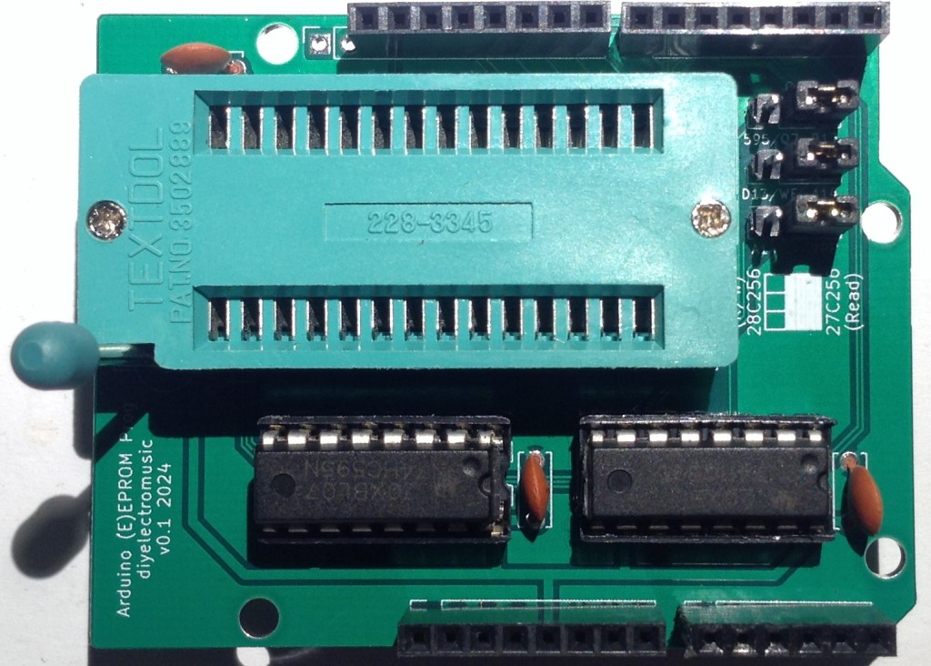
Here are some build photos.


Testing
I recommend performing the general tests described here: PCBs.
It is then worth temporarily tying the 8 data lines to 8 of the address lines via resistors so that the data read will be the same as the address on the chosen address lines. This would prove that everything is connected up sensibly.
It is also worth verifying the operation of OE (pin 22) and the state of VPP (HIGH) and CE (LOW).

In the photo, I’ve soldered up a simple test jig to tie D0-D7 to A0-A7 via resistors. I’m also using some “LED bytes” that have been doctored slightly to fit an Arduino, to indicate the status of the data lines which is pretty useful for seeing what is going on.
Then it would be useful to have a ROM for which the contents are known and then dump that entirely, for example to the Arduino serial console, to ensure that all data is being read correctly.
IMPORTANT: At this point in time, this board has not been tested for reading or writing to a 28Cxxx device. It has only been used for reading from a single 27C256 device.
PCB Errata
There is a problem with the trace that follows down the right-hand side of the board from D4 to the latch pin of the 595 (pin 12). It passes too close to one of the Arduino’s mounting holes and consequently is shorted to GND.
To fix it, it is possible to scrape off the track from around the hole and then use a patch wire. Having already built my board, this is the approach I took but if something conductive is used in the mounting hole in the future it may well short things out again.
It is probably better to cut the traces, prior to soldering any components, in the following places:


And then remake the connection with a patch wire which can be added as shown below:

My patched board:


Sample Applications
With the correct jumper configuration, this PCB should be able to be used with Ben Eater’s Arduino EEPROM Programmer code – but this is untested.
The code I’ve used as part of my DX100 investigation (details to follow) to read out the contents of a 27C256 compatible device can be found here: https://github.com/diyelectromusic/sdemp/tree/main/src/Misc/Arduino_EPROM_Reader.
Closing Thoughts
I’m not sure what I managed to disable in the design rules checker to miss the fact that that trace was too close to the hole. Oh well. I’ll have to investigate the board constraints I’ve been using.
As already mentioned, while this should in theory support reading and writing of 28Cxxx devices, as described in Ben Eater’s Github, at present it has only been used with 27C256 devices and only for reading.
I’ll attempt to get hold of some appropriate devices and give it a go at some point. Watch this space!
Kevin
