Here are the build notes for my RPi 400 MIDI and Audio PCB.
Warning! I strongly recommend using old or second hand equipment for your experiments. I am not responsible for any damage to expensive instruments!
In this case – inserting this pcb incorrectly (which unfortunately is possible with the RPi-400) could damage the RPi 400. See full post below for details.
If you are new to microcontrollers and single board computers, see the Getting Started pages.
Bill of Materials

- RPi 400 MIDI and Audio PCB (GitHub link below)
For the MIDI circuit
- 1x H11L1.
- 1x 74HCT14 (NB: Must be the HCT version, not the HC).
- 1x 1N914 or 1N4148 signal diode.
- 5x 220Ω resistors.
- 1x 470Ω resistor.
- 2x 100nF ceramic capacitors.
- Either: 3x 5-pin, 180 degree PCB-mount DIN sockets (see photos for footprint).
- Or: 3x stereo TRS PCB-mount sockets (see photos for footprint).
- Optional: 6-way DIP socket; 14-way DIP socket.
- 1x 2×20-way right-angle GPIO header socket.
For the additional DAC and MiniDexed sections:
- 1x GY-PCM5102 DAC module.
- 1x SSD1306 32×128 OLED display (pin order: GND-VCC-SCL-SDA).
- 5x 10nF ceramic capacitors.
- 2x 100nF ceramic capacitors.
- 1x switched rotary encoder (see photos for footprint).
- 2x slim toggle pcb-mount button switches (see photos for footprint).
- Optional: 4-way header socket for SSD1306 display.
For structural support when installed:
- 2x 2.5mm, 6mm nylon spacers
- 2x 2.5mm nylon nuts

Build Steps
Taking a typical “low to high” soldering approach, this is the suggested order of assembly:
- All resistors and diode.
- DIP sockets (if used) and TRS sockets (if used).
- Disc capacitors.
- GY-PCM5102 module (if used) – check that the solder jumpers on the back (see below).
- Buttons (if used).
- 4-way SSD1306 header socket (if used).
- GPIO headers.
- DIN sockets.
- Rotary encoder.
As mentioned in the design notes, it is possible to install the three main sections of the PCB independently depending on what is required:
- The MIDI circuits.
- The PCM5102 DAC.
- The MiniDexed IO components (display, encoder, buttons).
If a DIP socket is used for the 74HCT14 the to install the SSD1306 display will probably require a 4-way header socket in order to lift it high enough to avoid the installed 74HCT14 and to not negate any benefits of having the chip in a socket!
If the H11L1 and 74HCT14 are soldered directly to the board then a SSD1306 with extended pin headers should be adjustable enough to be soldered over the other components.
The capacitors that are labelled “10p” are actually 10nF capacitors. This is an error in the silkscreen.
Here are some build photos for a complete build with all sections complete.


At this point the MIDI sections are complete and it is possible to now install the TRS or DIN sockets and the GPIO header if a MIDI only board is required.


To continue building the DAC and IO sections see below.
Note check the PCM5102 jumper settings before fixing – more here. Also note how the capacitor for the PCM5102 is folded down underneath the board.


At this point the TRS or MIDI sockets can be installed.

Once complete, it is strongly advised to add a couple of 2.5M 6mm spacers to the middle of the PCB in order to support it when plugged into the RPi 400. This is particularly important if using a switched rotary encoder and the buttons.
As one of the holes for the spacers is under the corner of the PCM5102, it might need trimming down slightly to fit without pushing the PCM5102 upwards. In my case I had to cut the thread down slightly as shown in the photos below.


Here is the final board.


Testing
I recommend performing the general tests described here: PCBs.
Once the above tests were complete, I tried the board with a Raspberry Pi 3A+ on the basis that if something went wrong it would cost me a lot less to replace a 3A+ than my new RPi 400.
Care must be taken to orient the board correctly though when not using a RPi 400 – see photos below.
Once all seems to be functioning, I switched to my Raspberry Pi 400.
IMPORTANT: Additional care must also be taken when installing in a RPi 400 as it is quite possible to plug the board in “one pin out”. If this happens, then there is a distinct risk of connecting one of the 5V GPIO pins to GND which would damage the RPi 400.

With hindsight, the use of a keyed header socket (assuming they exist in right-angled, pcb-mounted format) would stop this happening.
If I rebuild this board, then I might leave pin 4 5V unconnected to prevent this happening. I don’t think any other power pins are adjacent to GND, although it still leaves the possibility of feeding a HIGH GPIO directly to GND in other places.
PCB Errata
There are the following issues with this PCB:
- As mentioned before, the capacitors labelled “10p” are really “10n”.
- The pcb slightly overlaps the uSD card slot on the RPi-400 which means it can’t be removed when the pcb is installed.
- Inserting incorrectly could connect GPIO 5V to GND and damage the RPi 400.
Sample Applications
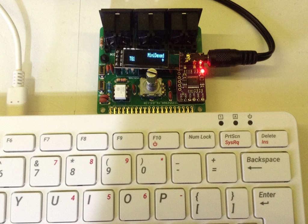
MiniDexed Raspberry Pi 400
The board is essentially a mirror of my MiniDexed Raspberry Pi IO Board physically arranged to support the Raspberry Pi 400 form-factor.
Below are the key minidexed.ini configuration settings that allows the RPi 400 to act as a MiniDexed synth with this board.
The MIDIThru setting is not required for general operation but can be used to turn on software MIDI THRU between the IN and OUT ports.
Also, MIDIThru can be used to direct the RPi 400 keyboard to the MIDI OUT port, turning it into a MIDI controller. The internal keyboard is device “ukbd1” which needs linking to “ttyS1” for the MIDI interface.
SoundDevice=i2s
#MIDIThru=ttyS1,ttyS1
MIDIThru=ukbd1,ttyS1

LCDEnabled=1
SSD1306LCDI2CAddress=0x3C
SSD1306LCDWidth=128
SSD1306LCDHeight=32
SSD1306LCDRotate=0
SSD1306LCDMirror=0

LCDColumns=20
LCDRows=2

ButtonPinPrev=0
ButtonActionPrev=
ButtonPinNext=0
ButtonActionNext=
ButtonPinBack=5
ButtonActionBack=click
ButtonPinSelect=11
ButtonActionSelect=click
ButtonPinHome=6
ButtonActionHome=click
ButtonPinShortcut=11

EncoderEnabled=1
EncoderPinClock=10
EncoderPinData=9
The built-in keyboard can be used as a simple 2-octave music keyboard to play the synth as follows:

Raspberry Pi 400 MIDI and Audio Interface
The board can be used as a MIDI and audio interface for the standard Raspberry Pi 400 OS too.
The basic idea is to use a I2S DAC overlay for the PCM5102 and to enable the serial port, but not the serial console, in the raspi-config and map MIDI onto it in some capacity.
Enabling the PCM5102 Sound
The full instructions are the same as described here: https://learn.pimoroni.com/article/raspberry-pi-phat-dac-install
But the short version (for 32-bit Raspberry Pi OS “bullseye”) is as follows.
Edit /etc/config.txt and comment out or add the following:
# dtparam=audio=on
dtoverlay=hifiberry-dac
There are other settings in there related to I2S but these can be ignored as the overlay file will include everything it needs. Note: commenting out the audio=on line will disable the built-in audio via the bcm device in the Raspberry Pi.
Then create an /etc/asound.conf file with the following:
pcm.!default  {

 type hw card 0

}

ctl.!default {

 type hw card 0

}
According to this document, this tells ALSA (the Linux sound system) to override its own default with hardware card 0, which is now the PCM5102. This can be confirmed using the command:
pi@raspberrypi:~ $ cat /proc/asound/cards
 0 [sndrpihifiberry]: RPi-simple - snd_rpi_hifiberry_dac
                      snd_rpi_hifiberry_dac
 1 [vc4hdmi0       ]: vc4-hdmi - vc4-hdmi-0
                      vc4-hdmi-0
 2 [vc4hdmi1       ]: vc4-hdmi - vc4-hdmi-1
                      vc4-hdmi-1
pi@raspberrypi:~ $
For it to work though I have to then select the “snd_rpi_hifiberry_dac” option in the “Device Profiles” by right-clicking on the Raspberry Pi OS Desktop “sound” icon in the tray (next to the clock).

Enabling Serial (UART) MIDI
Serial MIDI is linked up to the Raspberry Pi’s GPIO TX/RX ports on pins 14 and 15. But by default there are a couple of issues with just hooking these up to a MIDI interface:
- They are usually either expected to be used with a serial console or configured (apparently) for a faster Bluetooth link.
- The supported baud rates don’t include the standard MIDI 31250 baud.
- By default there is nothing that will connect a UART based serial port to ALSA to allow it to be used.
Details of how to solve this can sort of be found around the Internet, but I’ve not found a complete “just do this and everything works, and this is why” document. The official Raspberry Pi documentation for the UART can be found here: https://www.raspberrypi.com/documentation/computers/configuration.html#configuring-uarts (although to be honest, I didn’t quite follow most of it myself… primary UARTs? Hmm)
Other references:
- https://www.instructables.com/PiMiDi-A-Raspberry-Pi-Midi-Box-or-How-I-Learned-to/
- https://gist.github.com/CarloCattano/8c01a6dea6ecbb459acd0b6bcd752ea6
- https://www.samplerbox.org/article/midiinwithrpi
First enable the serial port and disable the console. This can be done by editing /boot/config.txt directly, but can also be done from the Raspberry Pi Configuration GUI tool.

Then in /boot/config.txt these additional updates are required:
enable_uart=1
dtoverlay=miniuart-bt
dtoverlay=midi-uart0
The first is probably already there if the serial port was enabled using the GUI. The second one apparently switches the internal Bluetooth over from using TX/RX on pins 14/15 to using ttyS0 (it is also possible to disable it completely with “disable-bt”). This frees up ttyAMA0 (TX/RX) for our use, which is the first UART on the PL011 peripheral on the bcm chip. The last setting includes some magic to tweak the clocks and baud rates so that the standard rate of 38400 will actually come out at the MIDI rate of 31250.
Details of each of these overlays can be found in the Raspberry Pi documentation (the README) here: https://github.com/raspberrypi/firmware/tree/master/boot/overlays and details of how the UARTS are set up and used on the different Pi versions, and which options are available, can be found here: https://www.raspberrypi.com/documentation/computers/configuration.html#configuring-uarts
Note: there are variants of midi-uart for other UARTs (which apparently can be enabled on a RPi 4) and a special midi-uart0-pi5 version for the Raspberry Pi 5.
This should have enabled the primary UART on TX/RX (pins 14,15) to be available with a suitable MIDI baud rate. But to use it, that serial port needs linking up to the operating systems sound setup.
Apparently the most common way to do this appears to be to use the ttymidi tool, which I guess fulfils a similar function to hairless-midi on a Windows PC (although I note hairless says it supports Linux too, even though it too recommends ttymidi!).
Unfortunately there doesn’t seem to be a ready-made version just to install, so it has to be built. The instructions from here worked fine for me:
$ sudo apt-get install libasound2-dev


$ wget http://www.varal.org/ttymidi/ttymidi.tar.gz


$ tar -zxvf ttymidi.tar.gz


$ cd ttymidi/


$ make


$ sudo make install
Once installed this needs to be started to connect the serial port to ALSA:
$ ttymidi -s /dev/ttyAMA0 -b 38400 -v
This provides the serial port and baud rate (remember 38400 has been tweaked to really be 31250 “on the wire”). The “v” option means it will dump any messages to the console. An optional “n” option can be used to give the link a nice name that can be used later. Without it, it defaults to “ttymidi”.
Two additional, useful tools to install (using the Raspberry Pi Add/Remove Software tool) are pmidi and midisnoop. pmidi can be used to list MIDI devices.
pi@raspberrypi:~ $ pmidi -l

 Port     Client name                       Port name

 14:0     Midi Through                      Midi Through Port-0

128:1     ttymidi                           MIDI in

pi@raspberrypi:~ $
The ALSA tool aconnect can also list available ports:
pi@raspberrypi:~ $ aconnect -l

client 0: 'System' [type=kernel]

    0 'Timer           '

    1 'Announce        '

client 14: 'Midi Through' [type=kernel]

    0 'Midi Through Port-0'

client 128: 'ttymidi' [type=user,pid=2619]

    0 'MIDI out        '

    1 'MIDI in         '

pi@raspberrypi:~ $
MIDIsnoop can be configured to use these ALSA ports and then can be used to show everything working.

How to actually use the ports I’ll might come back to, but in essence that becomes a tutorial in how to use ALSA and sound on Linux and there are lots of tutorials about that out there already.
At some point I’d like the above to all happen automatically on startup so that ttymidi is running and available to ALSA. That should be possible to add to one of the startup scripts, but that is left as an exercise for the reader (i.e. I haven’t looked that up yet).
Closing Thoughts
The “off by one” possibility of error when plugging the board in is concerning. I’d not anticipated that! But by being careful that should be manageable.
I also wasn’t anticipating not being able to unplug the uSD card! Oh well.
Apart from that, I’m really pleased with how it works.
At some point I might return to this and detail how to drive the display from Raspberry Pi OS itself as that would be a nice way to finish things off.
Kevin
