Here are the build notes for my RPi Zero MiniDexed IO Board PCB.

Warning! I strongly recommend using old or second hand equipment for your experiments. I am not responsible for any damage to expensive instruments!
If you are new to microcontrollers and single board computers, see the Getting Started pages.
Bill of Materials

- RPi Zero MiniDexed IO Board PCB (GitHub link below)
- SSD1306 OLED 128×32 I2C display (pinout: GND-VCC-SCL-SDA).
- Optional: GY-PCM5102 I2S DAC module.
- 2x 100nF ceramic capacitor.
- 5x 10nF ceramic capacitor.
- 1x Switched rotary encoder (PCB mount, see photos for footprint).
- 2x miniature toggle switches (PCB mount, see photos for footprint).
- 1x 4-way header socket.
- 1x 2×20 GPIO header socket.

Build Steps
Taking a typical “low to high” soldering approach, this is the suggested order of assembly:
- Disc capacitors.
- Button switches.
- GY-PCM5102 module (if used).
- 4-way header for display.
- GPIO header.
- Rotary encoder.
Build Options:
- With DAC: As described below with a GY-PCM5102 module on the board. The display will have to be fitted in a 4-way header socket and raised above he PCM5102 once fitted.
- No DAC: It is possible to use a PWM audio add-on for the Zero and not bother with a DAC. More details here: Raspberry Pi Zero PWM Audio Interface.
- External I2S DAC: It is possible to use something like the Pimoroni Audio DAC SHIM between the Zero and the MiniDexed IO board. More details here: A DX7 USB Dongle.
Note: in the case where the SSD1306 is soldered directly to the board, e.g. if no PCM5102 is used, the 100nF ceramic capacitor for its supply pins will have to be bent over flat prior to mounting the display.
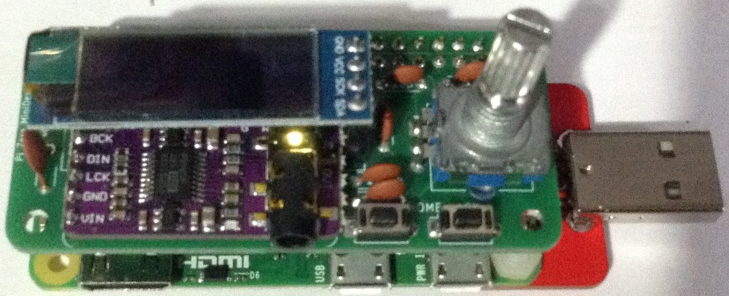
Here are some build photos.


Prior to soldering on the GY-PCM5102 module, the jumpers on the rear of the board may need to be configured. Sometimes they are soldered (left) and sometimes use zero-ohm SMT resistors (right), but the configuration required is 1=L, 2=L, 3=H, 4=L.


Only the 6-way connector is used for connection to the board, but it is recommended that at least a single additional header pin is used on the 9-way header to help physical stability of the final build.


This can be used with any Raspberry Pi, but my main aim was for something that could be used with a Pi Zero acting in USB Gadget Mode for example, with my DX7 USB Dongle as shown below.
Testing
I recommend performing the general tests described here: PCBs.
Once assembled, the correct MiniDexed configuration is required, as described below.
PCB Errata
There are the following issues with this PCB:
- The 5 debouncing capacitors for the encoder and switches are listed on the board as “10p” but they should be “10n” – i.e. 10nF ceramic capacitors.
Enhancements:
- Additional GPIO headers could be added for further expansions – e.g. more buttons.
MiniDexed Configuration
The key elements of the minidexed.ini configuration required to support this board are as follows.
# If in USB Gadget mode - see A DX7 USB Dongle.
USBGadget=1

# Either pwm or i2s
SoundDevice=i2s

LCDEnabled=1
SSD1306LCDI2CAddress=0x3C
SSD1306LCDWidth=128
SSD1306LCDHeight=32
SSD1306LCDRotate=1
SSD1306LCDMirror=0
LCDColumns=20
LCDRows=2

ButtonPinPrev=0
ButtonActionPrev=
ButtonPinNext=0
ButtonActionNext=
ButtonPinBack=5
ButtonActionBack=click
ButtonPinSelect=11
ButtonActionSelect=click
ButtonPinHome=6
ButtonActionHome=click
ButtonPinShortcut=11

EncoderEnabled=1
EncoderPinClock=10
EncoderPinData=9
Closing Thoughts
Whilst it is somewhat irritating to have made the 10p/10n mistake yet again, I’m quite pleased with how these boards have come out.
I have a stackable TRS MIDI interface in the works too which should be able to work with this IO board too.
Kevin

@diyelectromusic.wordpress.com Amazing how thorough your post is
LikeLiked by 1 person
Remote Reply
Original Comment URL
Your Profile
Why do I need to enter my profile?
This site is part of the ⁂ open social web, a network of interconnected social platforms (like Mastodon, Pixelfed, Friendica, and others). Unlike centralized social media, your account lives on a platform of your choice, and you can interact with people across different platforms.
By entering your profile, we can send you to your account where you can complete this action.
Hi Kevin, great project! I’d like to add Midi input to this PCB-version. Can you provide KiCad or Eagle schematics and layout please? I don’t have a commercial interest. I’d just like to build one for myself.
Best regards,
Simon
LikeLike
Yes sure – just ping me an email diyelectromusic at gmail and I’ll see what I can do. I trust you’ve spotted my separate Pi Zero MIDI board?
LikeLike