I have a need to route MIDI to several Raspberry Pi boards at the same time, so I’ve hacked together a variant of my MIDI Matrix Patch Bay to give me a 3.3V level serial MIDI THRU interface.
I’ve used it for my 8-way Raspberry Pi V1 MiniDexed in the following video.
Warning! I strongly recommend using old or second hand equipment for your experiments. I am not responsible for any damage to expensive instruments!
These are the key tutorials for the main concepts used in this project:
If you are new to microcontrollers and electronics, see the Getting Started pages.
Parts list
- MIDI Matrix Patch Bay INPUT board PCB
For the MIDI circuit:
- 1x H11L1 optoisolators.
- 2x 74HC14 (HC or HCT variants).
- 1x 1N914 or 1N4148 signal diodes.
- 1x 220Ω resistors.
- 1x 1K resistors.
- 3x 100nF ceramic capacitors.
- 1x 3.5mm, stereo TRS sockets, PCB mounted (see photos for footprint).
- Optional: 1x 180, 5-pin DIN sockets, PCB mounted (see photos for footprint).
- Optional: pin headers.
- Optional 1x 6-pin DIP sockets.
- Optional 2x 14-pin DIP sockets.
- Pin headers.
For the 3V3 power circuit:
- TL1117 3.3V regulator (the fixed kind, not the configurable kind).
- 1x 100nF ceramic capacitor.
- 1x 10uF electrolytic.
- 1x 100uF electrolytic.
- Barrel jack socket.
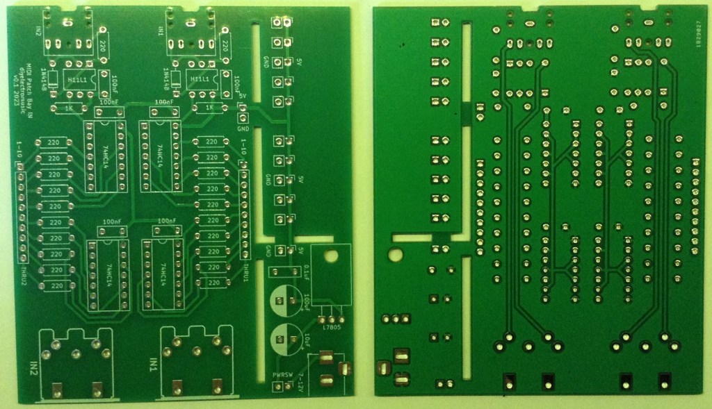
The Circuit
The INPUT board for my MIDI patch bay gives two MIDI INPUT channels, each broken out to 10 MIDI THRU channels. In my case I just want a single channel so will be using half of the INPUT board and the power supply section.
But as I want to provide a direct serial link to a Raspberry Pi, I need two things:
- I don’t need a full MIDI OUT stage, so will be taking the IO level directly from the 74HC14 inverters.
- I need it to work with 3V3 logic voltage levels.
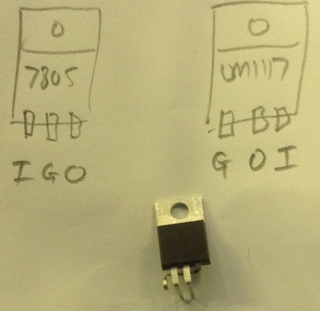
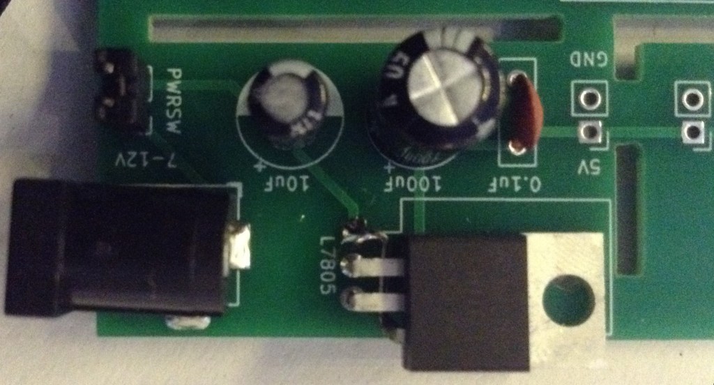
The latter can be solved by using a 3V3 regulator to power the whole circuit and running the inverters and optoisolator at 3V. But the power supply was designed for a LM7805 regulator with a TO-220 footprint and whilst it is possible to get a 3V regulator in TO-220 the pinouts are different!
As this is a one-off, I’ve opted to reuse one of my spare PCBs regardless and used the following, completely hacky solution… It works for me, but I’m not sure I could recommend it to anyone else 🙂
I started populating the lower half of the PCB (I only need one MIDI circuit), but then decided it was actually a lot easier to have used the upper half! So I ended up populating that too for convenience and then ignoring the lower half.

Build notes:
- As mentioned, the LM1117 is offset to align the pins with the LM7805 footprint.
- I’ve just used wire links in place of the 220Ω resistors that would have been used on the MIDI THRU outputs if I was using a full MIDI OUT stage.
- I’ve added header pins in the range of (optional) GND connections linked to the PSU part of the PCB.
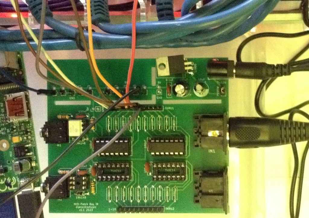
- I used both TRS and DIN MIDI sockets, although I’m only at this stage planning on using the DIN MIDI for now.
- The last photo shows both MIDI channels populated, but as already mentioned I’m only a actually using the top one. The lower half has no chips installed.
- The whole thing can be powered using a centre-positive barrel jack connector. In the last photo I’m using a USB A to barrel jack lead, so am powering it from 5V.
Closing Thoughts
This is not really meant to be a serious proposition, but it was something I needed and I had some spare PCBs that were very close, so I just made do to solve my specific problem.
And it worked for me.
But of course, this is very definitely a “only use with your expensive Raspberry Pi or musical instruments if you know what you are doing” project.
Kevin
