The Atari Punk Console is a bit of a “Hello World” build for DIY analog synthesizer fans. I looked up the circuit and read a little about how they work for my 556 Timer Light Theremin project I found on ebay, but the main background can be found in the following:
- Atari Punk Console on sdiy
- Forest Mims’ Stepped Tone Generator on Wikipedia
- Making Music with an Atari Punk Console by Forest M. Mims III
- Notes and Volts analysis and explanation
There are many kits out there and as a relatively straightforward build to get started in electronic music this is a really fun one. Here are some I’d recommend if you want to just get hold of a kit directly:
I bought one of the RaKits APCs (it goes really well with their Baby 8 Sequencer too) and it is a lot of fun.
I quite liked the idea of the Oskitone one too, but they don’t ship to the UK. But as this is an opensource hardware project, full schematics are available, so I thought I’d have a go at building my own. This is the result.
- Here is the Atari Punk Console PCB Build Guide.
Warning! I strongly recommend using old or second hand equipment for your experiments. I am not responsible for any damage to expensive instruments!
If you are new to electronics, PCBs or microcontrollers, see the Getting Started pages.
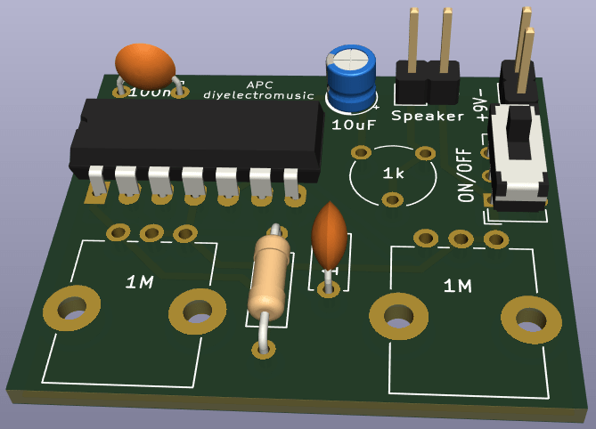
The Circuit

The Atari Punk Console, or “stepped tone generator” from the original design, uses two 555 timers with one modulating the other. In most designs this translates over to using a 556 dual timer and that is what I’m using here.
This is pretty much the Oskitone schematic ‘as is’. I’ve just tweaked it a little here and there. But the Oskitone circuit is pretty much the standard APC circuit you can find all over the Internet.
As to how it works in detail, again refer to one of the many guides that exist, or even go back to Forest M. Mims’ own words.
PCB Design

In my own version of the PCB, I’ve opted to keep it as small as possible and left the power and speaker off-board.
Here are some things to note about the circuit:
- The whole circuit runs at 9V so can be run simply from a 9V battery.
- The footprint for the power switch is set at standard 2.54mm pitch so there should be many options available here.
- The speaker (following the Oskitone schematic) is sitting at 9V, so the electrolytic coupling capacitor is perhaps the opposite way to what one might expect, with the positive side being speaker side. I’ve just followed the schematic here too (not really being an electronics person myself).
- The output volume of the speaker is set using the 1K trim pot.
- I’m using old headphone speakers with an impedance of 30-40Ω.
I did wonder if an additional current-limiting resistor might be required to support the speaker, but with the 1K potentiometer and 10uF capacitor there is already some limiting going on.
Reading a little about the 555, it would appear that it can be expected to sink or source up to 200mA current.
With my headphone speakers, the maximum current, ignoring the capacitor, with the pot turned on full – i.e. zero resistance, will be (using Ohm’s law): 9V / 40Ω = 225mA.
Using a simple 8Ω speaker it is more like 9V/8Ω = 1.125A which is far too high, so additional resistors would be required (or the pot should never be turned to “zero”).
Basically I’ve not accounted for additional resistors with the speaker, so if they are required they wil have to be added separately.
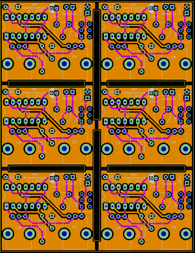
When it came to sending these off for manufacturing, I tiled them up to give me six boards within a 100x100mm footprint.
Closing Thoughts
I’ve deliberately gone for simplicity rather than robustness and I’m pondering using these as part of something wider at some point, hence getting plenty of PCBs ordered.
These boards have been sent to be manufactured by the Seeed Fusion PCB service, which I am happy to continue to recommend. They have been supported with discount vouchers that I’ve been sent by Seeed for my previous projects.
Kevin
