Here are the build notes for the RPi Dual MiniDexed PCB Design.
Warning! I strongly recommend using old or second hand equipment for your experiments. I am not responsible for any damage to expensive instruments!
These are the key tutorials for the main concepts used in this project:
If you are new to microcontrollers, see the Getting Started pages.
Bill of Materials
- RPi Dual MiniDexed PCB (GitHub link below).
- 2x GY-PCM5102 modules.
- 1x H11L1 optoisolator.
- 1x SSD1306 120×32 OLED display (pin order: GND-VCC-SCL-SDA).
- 1x 1N914 or 1N4148 diode or similar.
- Resistors: 1 each of 10Ω, 33Ω, 220Ω, 470Ω.
- 5x 100nF ceramic capacitor.
- 6x 10nF ceramic capacitor.
- 1x 100uF electrolytic capacitor.
- 1x switched rotary encoder.
- 3x tactile switches.
- 3x stereo TRS sockets (PCB mounted – see photos); OR
- 2x 5-pin 180 degree DIN sockets (PCB mounted – see photos).
- 1x 2.1mm barrel jack connector (PCB mounted – see photos).
- 2x 2×20 way GPIO extended header.
- 1x 6-way DIP socket (optional).
- Range of pin headers and jumpers.

Build Steps
Taking a typical “low to high” soldering approach, this is the suggested order of assembly:
- All resistors and diode.
- DIP socket (if used) and TRS sockets (if used).
- Tactile switches.
- Disc capacitors.
- Pin headers for use with jumpers.
- GY-PCM5102 and SSD1306 modules.
- Non-polar or electrolytic capacitor, barrel jack connector.
- Rotary encoder.
- DIN sockets (if used).
- GPIO headers.
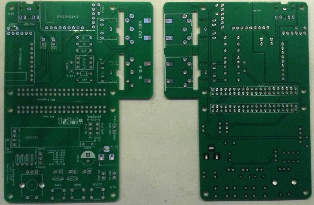
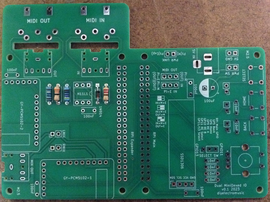
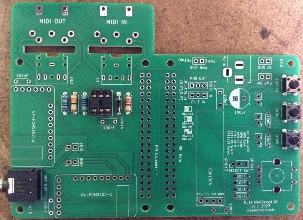
Here are some build photos.


When it comes to mounting the GY-PCM5102 modules, there are two things that must be done first:
- The appropriate jumpers must be configured.
- Pin headers must be added for the main 6-way connector and to support 4 pins for the audio interface.

The above photo shows a GY-PCM5102 ready for adding to the PCB. Both modules should be configured in the same way.


I use extended headers for the GPIO link to ensure adequate clearance between the PCB and the Pis, but you might be fine with normal headers. See how you go!
Configuration Options
There are several jumpers on the board as follows.

Power Jumpers/headers

The 5V/GND header is an alternative power input feed to the barrel jack connector. Either can be used. The PWR SW header allows the connection of an external power switch. This should just be jumpered over if a switch isn’t required.
The PWR LINK jumper ties the 5V GPIO lines of the two Raspberry Pis together. This should be linked with a jumper if the barrel jack or 5V header pins are going to power both Raspberry Pis. This should be removed if the Pis are going to powered independently – i.e. via their own USB power connectors.
MIDI Routing Jumpers

As descrbied previously there are three main MIDI routing options:
- IN -> Main; Main -> Expander; Expander -> OUT
- IN -> Main and Expander; Main -> OUT
- IN -> Main and Expander; Expander -> OUT
These three options are represented by the three silkscreen labels on the PCB. The first option is required for dual MiniDexed operation.
Other Jumpers/Headers
- LMIX/RMIX can be used to remove the passive mixing of the two PCM5102 signals. This is required if an external mixer is used from the onboard audio outputs of the two PCM5102 modules.
- SELECT SW can be used to route the SELECT switch to either GPIO 11 or GPIO 13. GPIO 11 is routed to the encoder switch, but GPIO 13 can be used to create a fourth independent switch.
- There are also three sets of header pins for connecting to external switches.
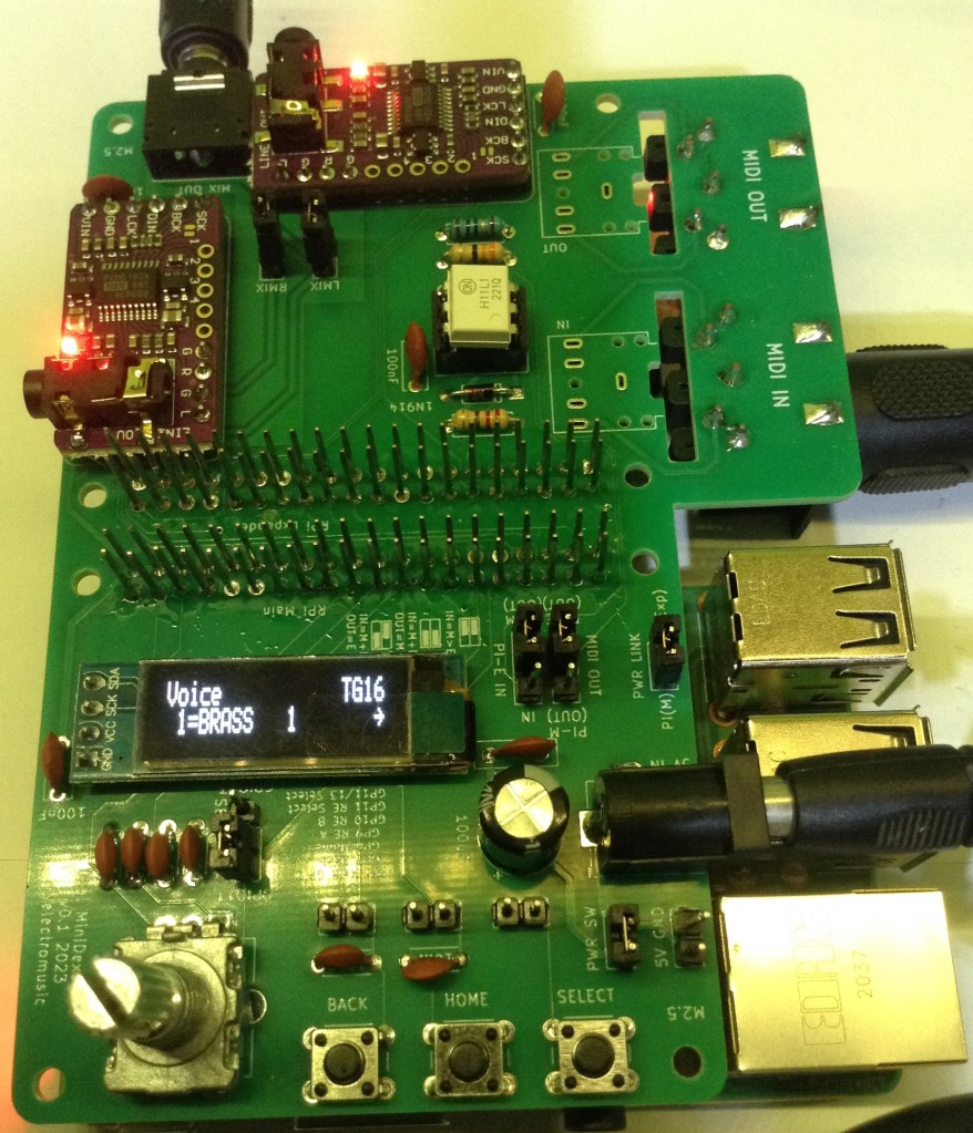
MiniDexed IO Configuration
Here are the MiniDexed configuration settings for the main RPi that is driving the user interface. The other settings can stay with their default settings.
SoundDevice=i2s
MIDIThru=ttyS1,ttyS1
LCDEnabled=1
SSD1306LCDI2CAddress=0x3C
SSD1306LCDWidth=128
SSD1306LCDHeight=32
LCDColumns=20
LCDRows=2
ButtonPinBack=5
ButtonActionBack=click
ButtonPinSelect=11
ButtonActionSelect=click
ButtonPinHome=6
ButtonActionHome=click
ButtonPinShortcut=11
EncoderEnabled=1
EncoderPinClock=10
EncoderPinData=9
Testing
I recommend performing the general tests described here: PCBs prior to connecting the Raspberry Pis. Then the following can be checked:
- Apply 5V power via the barrel jack or power header (with a jumper across the switch headers) and check for power on the PCM5102 and displays.
- Remove the “PWR LINK” jumper and install one Raspberry Pi as the “main” board running the standard MiniDexed firmware configured as described above. Connect audio to the MIX OUT. This should function as a normal stand-alone MiniDexed module.
- Remove the main RPi and plug it into the second (expander) RPi position. Set the “PI-E IN” jumper to the IN position. Connect audio to the MIX OUT. This should function as a headless, MIDI driven, MiniDexed.
At this point it should be possible to decide on a power configuration, configure the MIDI routing as required, and install two Raspberry Pis running the bespoke “16 TG Expander” build of MiniDexed for full operation as described below.
PCB Errata
There are no known issues with this PCB at the present time.
Enhancements:
- The silkscreen labels for the MIDI routing could be clearer.
Sample Applications
As indicated in the testing section, the Main RPI can act as a MiniDexed module in its own right, but the main application is with a custom build that supports a tone generator expander.
Details of that can be found here: 16 Tone Generator MiniDexed.
Closing Thoughts
This was always going to be a bit of a niche application, but it gives me a platform for experimenting now with my dual MiniDexed custom firmware.
Watch this space!
These boards have been manufactured using the Seeed Fusion PCB service, which I am happy to continue to recommend. They have been supported with discount vouchers that I’ve been sent by Seeed for my previous projects.
Although I’ve only used their PCB service, you can find links to all of their manufacturing services here.
Kevin