Here are the build notes for my XIAO MIDI Proto PCB.

Warning! I strongly recommend using old or second hand equipment for your experiments. I am not responsible for any damage to expensive instruments!
If you are new to microcontrollers, see the Getting Started pages.
Bill of Materials

- XIAO MIDI Proto PCB (GitHub link below).
- 1x H11L1 optoisolator.
- 1x 1N914 or 1N4148 diode or similar.
- Resistors: 1 each of 10Ω, 33Ω, 220Ω, 470Ω.
- 1x 100nF ceramic capacitor.
- 4x 7-way header sockets. Ideally “short profile” with plastic height of 5mm, see photo below.
- 1x 2×2 “spring loaded pogo-pin” header. Ideally the “A height” (i.e. from the bottom of plastic base to the top of spring-loaded contact) is 10mm. See photo below.
- 1x 2-pin tactile switch, see photo below.
- 2x 180 degree DIN sockets OR 2x TRS stereo PCB mount sockets (see photos for footprints).
- 1x 3-way pin header.
- Optional: 1x 2-way pin header.
- Optional: 6-way DIP socket.

Note that if normal profile 7-way headers are used then longer pogo-pins will be required in order to connect with the XIAO. I would imagine that common-sized headers may require 13 or 14mm pogo pins, but some experimentation may be required.

Build Steps
Taking a typical “low to high” soldering approach, this is the suggested order of assembly:
- All resistors and diode.
- DIP socket (if used).
- Ceramic capacitor.
- 7-way headers.
- Pogo-pin and normal pin headers.
- DIN sockets.
If “normal” 7-way header sockets are used then it may be necessary to leave the longer pogo-pin headers until after the normal pin headers, but before the DIN sockets.
The pin headers for the SWD and power links are optional.
If using external power via the 5V pin header, then this should be a stable, “as would be delivered via USB” 5V power input as it connects directly to the XIAO’s 5V power pin.
Here are some build photos.


Testing
I recommend performing the general tests described here: PCBs prior to plugging in the H11L1 and the XIAO.
Then basic testing can be continued by loading the Simple MIDI Monitor code and connecting up a MIDI IN and MIDI OUT device. MIDI should be automatically routed from the IN port to the OUT port and every time a MIDI message is received the orange LED on the XIAO should go off (the LED logic for the XIAO is opposite to an Arduino).
Prototyping Area In Use

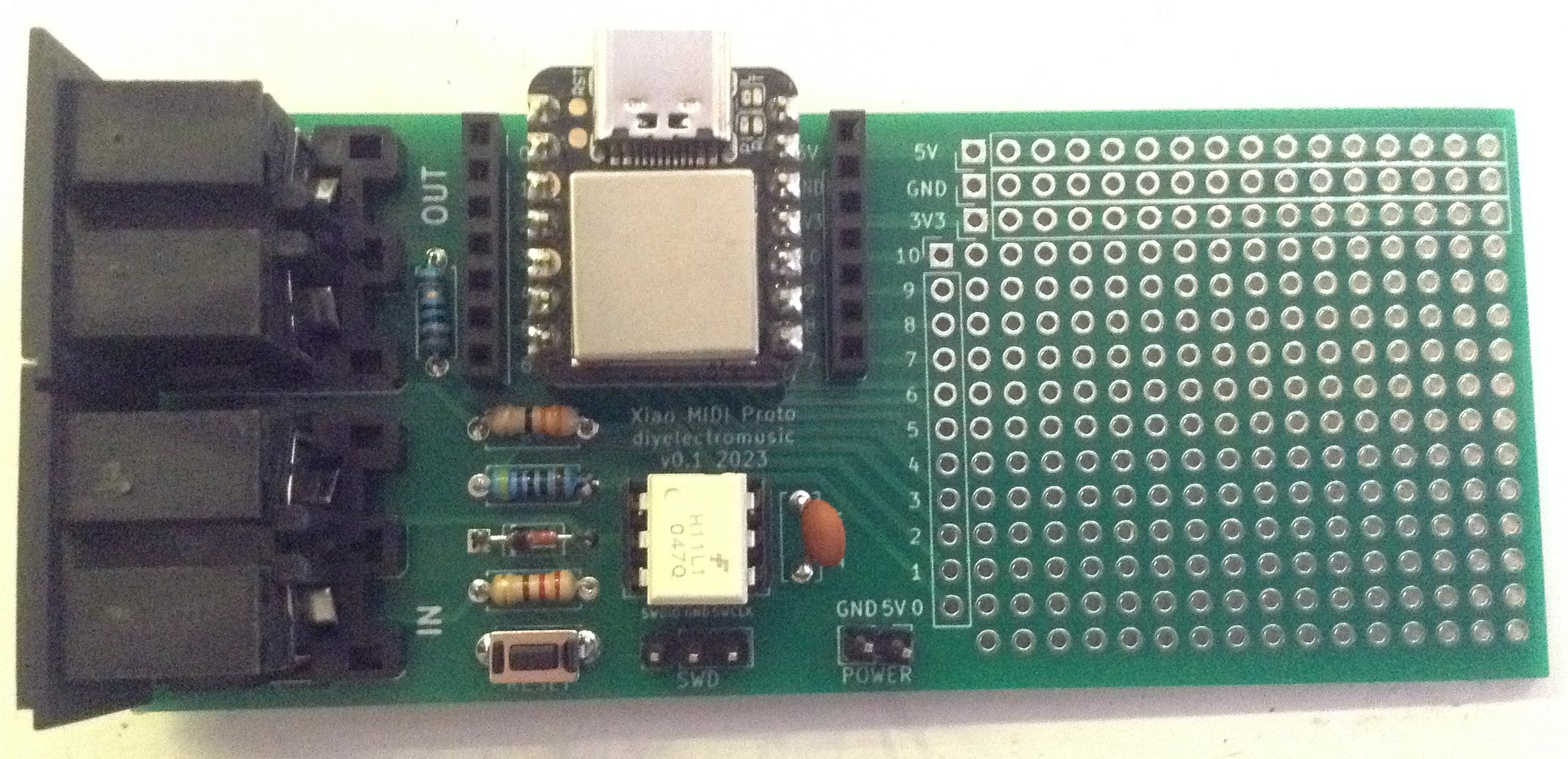
There are two ways to utilise the GPIO from the XIAO: there is an additional set of headers alongside the XIAO itself that can be used to link to jumper wires; and all GPIO are also linked to a vertical row next to the prototyping area (both highlighted in yellow above).
Note the labels on the prototyping area for 0-6 are back to front! Pin 6 is actually at the bottom.
In terms of power, there are rows for 5V, GND and 3V3 across the top of the prototyping area (highlighted in red above).
There are a few limitations;
- GPIO 6/7 are already wired directly into the MIDI interface, so whilst still broken out to the prototyping area, probably shouldn’t be used.
- The available power via the 5V and 3V3 links is limited to the power that the XIAO itself can provide. However it is possible to hook up an external 5V supply if that might be of use.
- All GPIO is assumed to be 3V3 as supported by the XIAO.
PCB Errata
There are the following issues with this PCB:
- The silkscreen labels for the IO breakouts near the prototyping area for A0 to A6 are back to front. Pin 6 is actually at the bottom and pin 0 is next to pin 7.
Enhancements:
- A proper MIDI OUT buffer stage.
- A MIDI signal LED could be added.
- It might be useful to add an I2C header in the future.
- A Grove style connector could be added.
- A “proper” power circuit with a barrel jack could be added.
Sample Applications
A number of applications are described in my series on the XIAO SAMD21, Arduino and MIDI.
Also see the CircuitPython USB to Serial MIDI Router.
Other XIAO Series Boards
The board should work with all versions of the XIAO series apart from the new ESP32S3 Sense (as it doesn’t have the same arrangement of pads underneath). If the pogo-pin headers are left out (so no reset switch or SWD header either) then it should also work with the Adafruit QT-Py boards too.
The following have been tested and known to work:
- XIAO SAMD21
- This is the board this was designed for. MIDI is on GPIO 6/7.
- XIAO RP2040
- MIDI is on GP0/1 in Circuit/Micropython, mapped on to the same pins 6/7 of the XIAO formfactor.
- XIAO ESP32C3
- There is no LED_BUILTIN defined.
- MIDI is on GP20/21 mapped onto pins 6/7.
- MIDI will be on Serial or Serial0 depending on the setting of “USB CDC On Boot” – if enabled, then Serial0 is used and MIDI must be initialised using:
MIDI_CREATE_INSTANCE(HardwareSerial, Serial0, MIDI);
#define LED_BUILTIN D10  // Attach an LED+Resistor to D10+GND
- Adafruit QT Py ESP32C3 – semi-working!
- This has the same provisos as the XIAO ESP32C3.
- BUT care must be taken that the pogo-pins don’t short anything on the underside of the board.
- I could not get MIDI TX working successfully. I can see a signal on the TX pin/MIDI DIN but it wasn’t registering as a MIDI message at the receiving end. MIDI RX seems to work fine.
Please Note: Other XIAO series or Adafruit QT Py (or similar XIAO form factor boards) have NOT been tested, but some may work… Feel free to let me know if you try them out!

Closing Thoughts
The pogo-pin arrangement, shamelessly copied from the official XIAO expander module, was a bit of an initial risk. Certainly getting the right height for the pogo-pins took a couple of tries, but having the reset switch makes using the XIAO so much easier. I’m annoyed about not spotting the pin labelling error!
I have wondered about a CircuitPython series using the XIAO, but as so many others have build MIDI CircuitPython devices, I’m not sure what I would add.
But regardless this could act as a MIDI device for many CircuitPython MIDI projects too if required. If this sounds interesting, I’d recommend exploring the Adafruit learning system searching for MIDI.
These boards have been manufactured using the Seeed Fusion PCB service, which I am happy to continue to recommend. They have been supported with discount vouchers that I’ve been sent by Seeed for my previous projects.
Kevin
