Here are the build notes for my Pico, Nano, Micro Keyboard Matrix PCB.
Warning! I strongly recommend using old or second hand equipment for your experiments. I am not responsible for any damage to expensive instruments!
These are the key Arduino tutorials for the main concepts used in this project:
- Keyboard Matrix Decode
- Toy Keyboard Tone Piano
- Pi Pico MIDI Matrix Decode
- Toy Keyboard Matrix Decode with the Pi Pico
If you are new to Arduino, see the Getting Started pages.
Bill of Materials

- Pico, Nano, Micro Keyboard Matrix PCB (GitHub link below)
- Optional: One or more of:
- 2x 20-way pin header sockets (for the Raspberry Pi Pico).
- 2x 15-way pin header sockets (for the Arduino Nano).
- 2x 12-way pin header sockets (for the Pro Micro).
- Optional: 2x 3-way pin headers (for POWER and SERIAL).
- 1x 8-way pin headers.
- 1x 12-way pin headers.

Build Steps
The microcontroller can be soldered directly to the board if required, or alternatively pin header sockets can be used. Only one set of pin headers (20-way, 15-way or 12-way) is actually required if the board will only ever be used with one type of microcontroller.
In these photos, I’ve soldered on all three sets of headers to allow for some simple experiments.
These are the key steps:
- Decide on the pin header socket configuration required.
- Solder on the pin header sockets or microcontroller as required.
- Solder on the 8-way and 12-way pin headers.
- If required, solder on the two 3-way pin headers.
Here are some build photos.


One trick to keeping pin header sockets aligned during assembly is to temporarily use some pin headers to keep them in place as shown above. Then one pin for each socket can be soldered down and the alignment and position checked. It is much easier to reheat and resolder an existing single joint whilst realigning a header at this stage then when several have been soldered down.


In the following examples I’ve shown how the Pico and a Nano could be used. Note that the Pico and Pro Micro are “USB to the left” and the Nano is “USB to the right”.

Testing
I recommend performing the general tests described here: PCBs.
PCB Errata
There are the following issues with this PCB:
- The “columns” are connected to A0 to A7 on the Nano, but A6 and A7 cannot be used as IO pins.
- The positioning of the Nano’s mini USB socket is not ideal when used with column 1 and the 5V header pins.
Enhancements:
- A different pin mapping for the Nano would make for a more useful matrix connection.
Sample Applications
Any of the keyboard matrix projects on my site could have benefited from this board. But each will need some tweaking to be used with the pinouts (listed once again below).

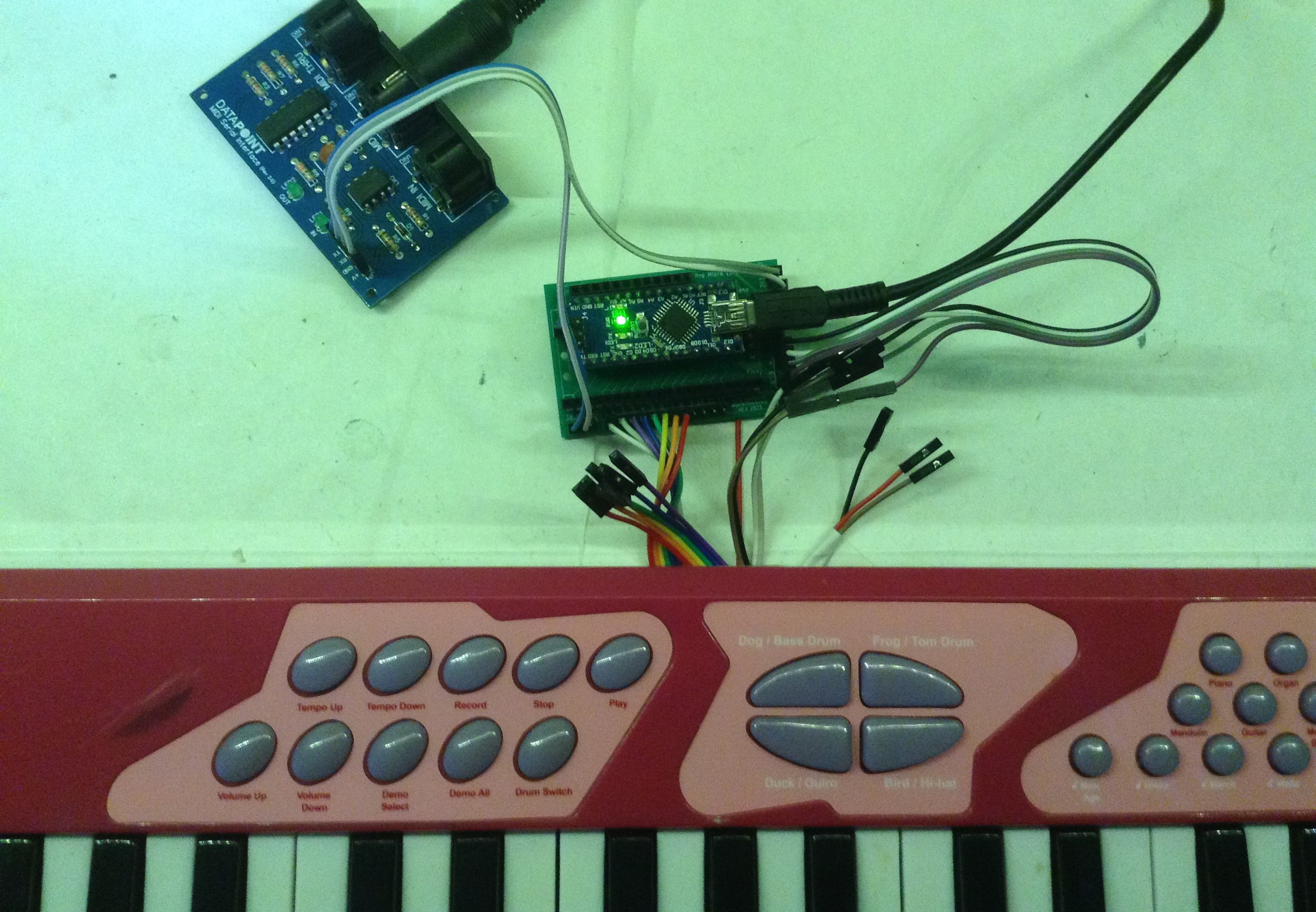
The video shows how my Toy Keyboard Tone Piano can be turned into a MIDI controller using this PCB and an Arduino Nano.
Note that there is no intelligence in this PCB – it is simply a breakout to the IO pins of the chosen microcontroller.
Closing Thoughts
I’m still rather annoyed about the Nano A6/A7 thing, but that was my fault for not double checking before sending everything off. Still it makes for a useful board for these kinds of experiments.
In future, the use of the Pro Micro would allow a USB MIDI controller, and the Pico should allow for much larger (12×8) keyboard matrices.
These boards have been manufactured using the Seeed Fusion PCB service, which I am happy to continue to recommend. They have been supported with discount vouchers that I’ve been sent by Seeed for my previous projects.
Kevin
