Here are the build notes for my Arduino Mozzi Experimenter Shield PCB.
Warning! I strongly recommend using old or second hand equipment for your experiments. I am not responsible for any damage to expensive instruments!
These are the key Arduino tutorials for the main concepts used in this project:
If you are new to Arduino, see the Getting Started pages.
Bill of Materials

- Arduino Mozzi Experimenter Shield PCB (GitHub link below)
- 1x 6N138 optoisolator
- 1x 4K7 resistor
- 1x 1.5K resistor (was 270Ω)*
- 4x 220Ω resistors
- 1x 330Ω resistor (was 75Ω)*
- 4x 10k linear (B) potentiometer (see photos and footprint)
- 1x 1N914 or 1N4148 signal diode
- 1x 100nF ceramic capacitor
- 1x 68nF ceramic capacitor
- 1x 10uF electrolytic or non-polar capacitor
- Optional: 8-pin DIP socket
- 2x 180 degree DIN PCB mounted sockets
- Pin headers and jumpers
- 1x 3.5mm stereo TRS audio jack socket, PCB mounted (see photos and footprint)
- A set of Arduino header pins or extended sockets
* See the discussion about values here: Arduino PWM Output Filter Circuit.

Build Steps
Taking a typical “low to high” soldering approach, this is the suggested order of assembly:
- All resistors and diode.
- DIP socket (if used) and TRS socket.
- Disc capacitors.
- 3-way jumper headers.
- If using extended Arduino headers, now is a good time to solder those.
- Non-polar or electrolytic capacitor.
- DIN sockets.
- Potentiometers.
- Arduino pin headers (if not already fixed as mentioned above).
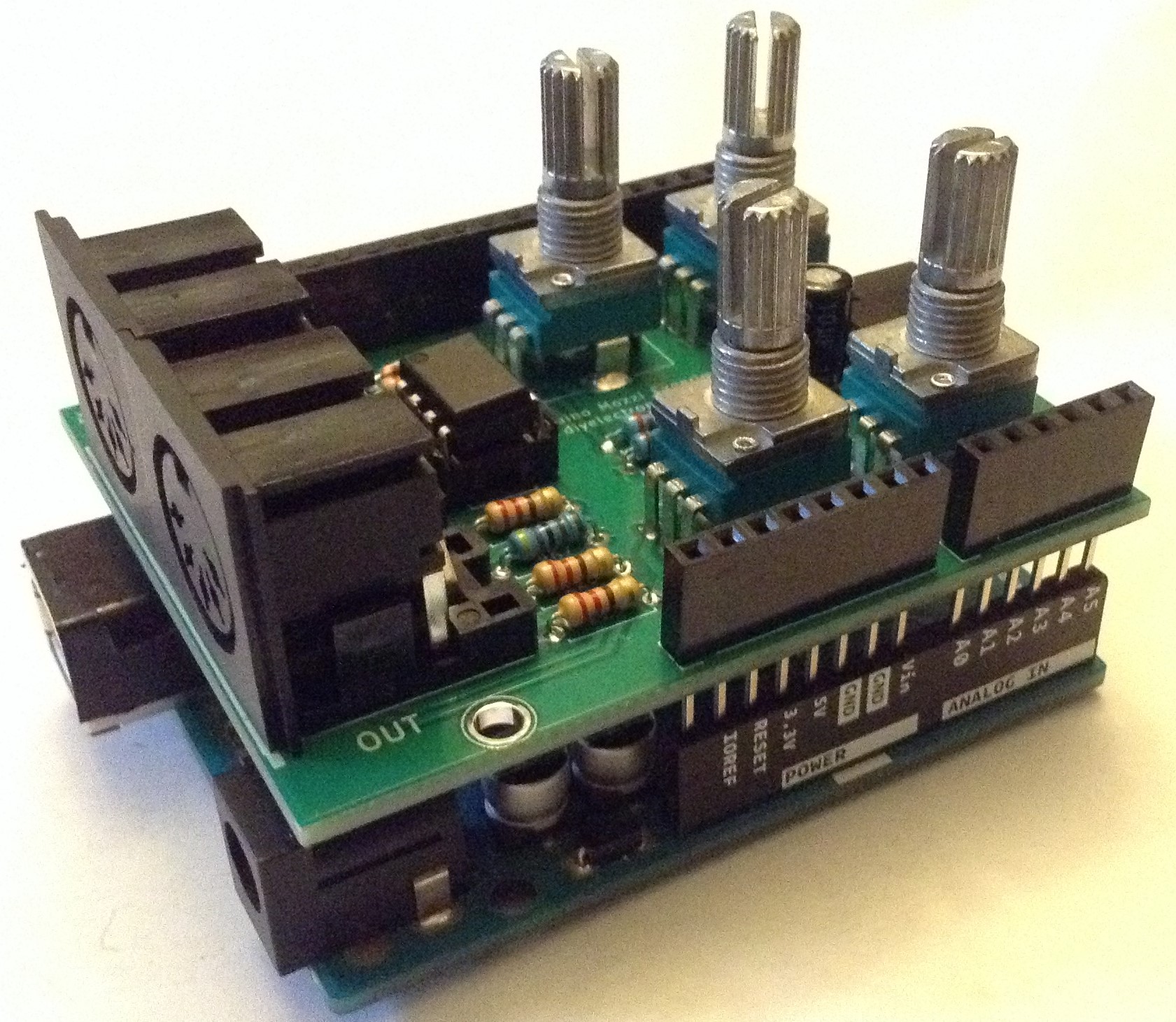
Here are some build photos (note I didn’t quite follow the above order – that is now recommended from experience!).


Testing
I recommend performing the general tests described here: PCBs.
PCB Errata
There are the following issues with this PCB:
- The potentiometers are “backwards” in that zero is fully clockwise and full is fully anticlockwise. I’d prefer them the other way round.
- The jumper headers are a little close to the MIDI DIN sockets to make changing them easy.
- The jumper headers ought to be labelled to indicate which position is “enabled”. It is actually on the silkscreen, but that gets covered over by the pin headers!
And whilst not an errata as such, the PWM filter works much better replacing the 270Ω and 75Ω resistors with 1.5K and 330Ω respectively.
Enhancements:
- Add MIDI TRS footprints in addition to MIDI DIN.
- Arrange the jumper pin headers so they could be replaced by a DPDT switch.
- Add pin headers to breakout the additional analog pins for extra pots.
- Add a jumper to all output from either D9 or D3.
Sample Applications
Here are some applications to get started with:
- Arduino PWM MIDI Synthesis with Mozzi
- Arduino Multi-pot Mozzi FM Synthesis – Revisited
- Arduino Mozzi Additive Synthesis
Closing Thoughts
I’m pleased with this board. It holds up to its purpose of allowing for some nice MIDI and Mozzi (or PWM) experimentation all in a single board.
It is actually quite similar to the official Arduino “Make your Uno” synth shield. The key difference being having only four pots, not five, but with the addition of MIDI and an audio output jack, rather than an amplifier and speaker.
These boards have been manufactured using the Seeed Fusion PCB service, which I am happy to continue to recommend. They have been supported with discount vouchers that I’ve been sent by Seeed for my previous projects.
Kevin
