This is the build guide for my Arduino Nano Multi-tone or PWM PCB.
Warning! I strongly recommend using old or second hand equipment for your experiments. I am not responsible for any damage to expensive instruments!
These are the key Arduino tutorials for the main concepts used in this project:
- Arduino PWM Sound Output
- Arduino Multi MIDI Tone Module
- Arduino MIDI Multi-Tone Module
- Arduino Multi Mozzi String Synth
If you are new to Arduino, see the Getting Started pages.
Bill of Materials

- Arduino Nano Multi-tone or PWM PCB (GitHub link below)
- 1x 100nF ceramic capacitor
- 1x 100uF electrolytic capacitor
- 1x 2.1mm barrel jack socket (PCB mount – see photo)
- 8x 15-way pin header sockets
- 8x jumpers
- pin headers
For tone speaker output:
- 12x 220Ω resistors
For PWM output:
- 4x 10K resistors
- 4x 1.5K resistors (was 270Ω)*
- 4x 330Ω resistors (was 75Ω)*
- 4x 68nF ceramic capacitor
- 4x 10uF electrolytic or non-polar capacitor
- 1x 3.5mm stereo TRS jack socket (PCB mount – see photo)
* See the discussion about values here: Arduino PWM Output Filter Circuit.
To use the board will also require up to four Arduino Nanos and a 500mA+ 7V+ DC PSU (centre positive). Then depending on the mode, either some loudspeakers (e.g. recycled 8Ω from a stereo or recycled headphone speakers) or some form of amplification for the jack socket PWM output. It will also require something to drive the 5V MIDI serial signal inputs.
This board does NOT contain a proper MIDI IN interface – deliberately so. It is designed for use with something else to general MIDI over 5V serial.

Build Steps
The board is all through-hole components and can be built using a “low to high” approach – solder on the low-fitting components first. This is the suggested order (assuming everything is being built):
- Resistors
- 3.5mm jack socket (if used)
- Ceramic capacitors
- Pin headers
- Barrel jack
- 15-way header sockets
- Electrolytic capacitors
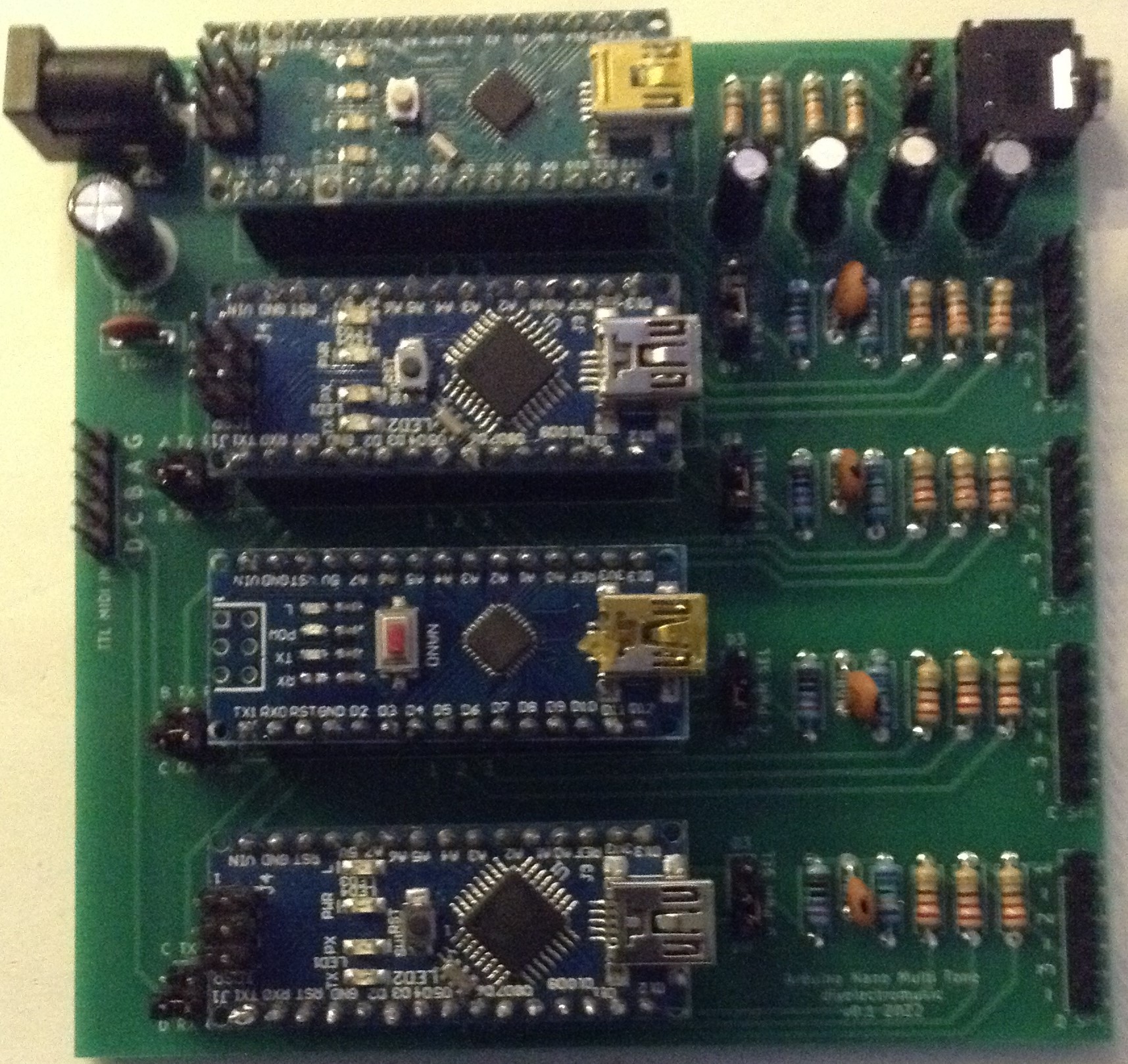
Here are some photos of the build in progress.


Testing
I recommend performing the general tests described here: PCBs.
Configuration
There are two sets of headers for further connectivity and three sets of jumpers on the board, in the positions highlighted below.

Connections:
The MIDI connector (far left) is for 5V level serial MIDI inputs. The board will support four independent MIDI serial links (A, B, C, D, one to each Nano) or a single MIDI serial link (A that is passed between Nanos). There is also a GND pin (G) which should be used to support a common GND between the sender and the Nanos.
The speaker connectors (far right) allow for up to three speakers to be connected to each Nano. There are six pins each, one for the signals from D4 (1), D5 (2), and D6 (3) and a GND connection (-) each.
Mono:
This is the simple one. This jumper allows the L/R channels of the TRS jack socket to be connected together, so that all four PWM outputs are mixed into a single mono signal to both channels. If the jumper is removed, then two of the PWM outputs go to L and two to R.
PWM Select:
This allows the PWM output pin to be selected for each Arduino Nano in dependently. The top jumper position selects D3 and the bottom selects D9.
RX Mode:
This is a little more complex. There are three modes for the RX pin of each of Nano B, C and D. It can be connected to one of the following:
- The corresponding TTL MIDI input (D, C, B).
- The previous Nano’s TX pin. This allows “daisy chaining” relying on software MIDI THRU on each Nano to pass data onto the next. The chain goes:
- TTL MIDI IN A -> Nano A RX;
- Nano A TX -> Nano B RX;
- Nano B TX -> Nano C RX;
- Nano C TX -> Nano D Rx.
- The previous Nano’s RX pin. This allows all nanos to receive the same MIDI IN signal via TTL MIDI IN A.
Nano A’s RX pin is always connected to the TTL MIDI IN A. Here are the three configurations, illustrated using the jumper block for Nano B:

PCB Errata
Nothing obvious has been uncovered so far, but if I was updating the board, I might consider the following:
- I meant this to be powered by a centre-positive barrel jack, but got it wrong! You must use a centre-negative (sorry).
- Adding a 5V pin to the MIDI links to allow for a MIDI module to be directly connected.
- Reposition the components near the Arduino USB ports to make it easier to plug in USB (although that should probably only be done one at a time.
- Label the speaker outputs with the digital pin numbers.
- The RX mode jumpers are a little close the Nanos so would benefit from being placed slightly further out.
And whilst not an errata as such, the PWM filter works much better replacing the 270Ω and 75Ω resistors with 1.5K and 330Ω respectively.
Closing Thoughts
I’m really annoyed about getting the polarity of the barrel jack wrong, but other than that I’m really pleased with how this turned out. This will be really useful for my Lo-Fi Orchestra.
These are some of the projects that could be used with this board:
- Arduino PWM Sound Output
- Arduino Tones – A New, New Hope
- Arduino Nano Multi-pot FM and String Synthesis
These boards have been manufactured using the Seeed Fusion PCB service, which I am happy to continue to recommend. They have been supported with discount vouchers that I’ve been sent by Seeed for my previous projects.
Kevin
