This is the build guide for my Arduino Audio Experimenter Shield PCB.
Warning! I strongly recommend using old or second hand equipment for your experiments. I am not responsible for any damage to expensive instruments!
These are the key Arduino tutorials for the main concepts used in this project:
If you are new to Arduino, see the Getting Started pages.
Bill of Materials

This board has four key circuits which are largely independent, so it isn’t necessary to build them all. The core components required are:
- The Arduino Audio Experimenter Shield PCB (GitHub link below).
- Pin headers and jumpers
- 1x 3.5mm stereo audio jack socket, PCB mounted (see photos and footprint)
- A set of Arduino header pins or extended sockets
Note: If using a USB-A style Arduino Uno it may be advisable to use extended pin headers. At the very least, the top of the USB socket must be insulated to prevent it touching the underside of the PCB.
For the MIDI circuit
- 1x 6N138 optoisolator
- 4x 220Ω resistors
- 1x 4K7 resistor
- 1x 1N914 or 1N4148 signal diode
- 1x 100nF ceramic capacitor
- Optional: 8-pin DIP socket
- 2x 180 degree DIN PCB mounted sockets
For the R2R ladder:
- 9x 20K resistors
- 7x 10K resistors
For the PWM output:
- 1x 1.5K resistor (was 270Ω)*
- 1x 330Ω resistor (was 75Ω)*
- 1x 68nF ceramic capacitor
- 1x 10uF electrolytic or non-polar capacitor
* See the discussion about values here: Arduino PWM Output Filter Circuit.
For the MCP4725 DAC:
- 1x MCP4725 DAC module, pinout: OUT-GND-SCL-SDA-VCC-GND
- Optional: 1x 6-way header socket

Build Steps
The board is all through-hole components and can be built using a “low to high” approach – solder on the low-fitting components first. This is the suggested order (assuming everything is being built):
- All resistors and the diode
- 8-way DIP socket (if used)
- Both ceramic capacitors
- 3.5mm jack socket
- The five jumper pin headers
- 6-way header socket for the MCP4725 (if used)
- 10uF capacitor
- DIN sockets
- Arduino pin headers
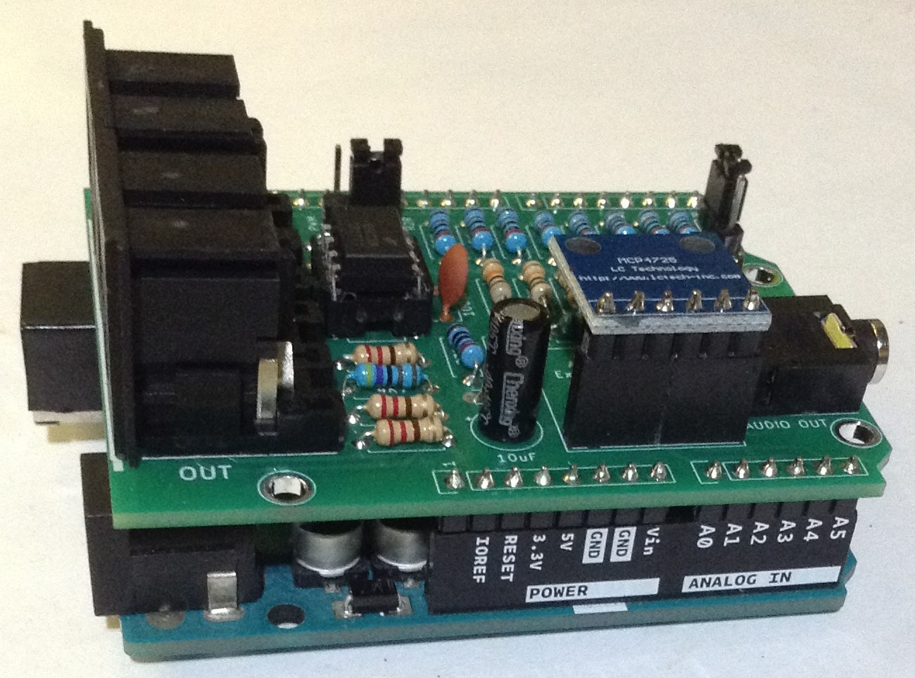
Here are some photos of the build in progress.


Important Note: I got the orientation of the MCP4725 wrong! The pins are the wrong way round. There are several solutions to this:
- Mount the MCP4725 so it overhangs the Arduino’s headers.
- Mount the MCP4725 vertically using right-angled header pins.
- Mount the MCP4725 upside down.
I opted for the latter.


Testing
I recommend performing the general tests described here: PCBs.
Configuration
As previously mentioned there are four key sections of the board: MIDI, R2R, PWM, and the MCP4725 as highlighted below:

The configuration jumpers select the following:
- MIDI enabled/disabled (it has to be disabled to allow sketches to be uploaded).
- Use of D3 and D9: either for PWM output or the R2R ladder.
- Audio output source: R2R, PWM or the DAC.
Note that it is assumed that the DAC will be removed if not in use – i.e. if the R2R or PWM output is configured.
The following photos show the three modes of operation.


The following projects can be used to test the board is working:
- Simple MIDI Monitor
- Use “as is” to test MIDI routing from IN to OUT. The LED will flash on reception of MIDI note messages.
- Arduino MIDI R2R Digital Audio – Part 2
- Playing MIDI notes into the Arduino will generate a tone.
- Arduino PWM Sound Output
- Configure PIN_9_PWM_OUTPUT or PIN_3_PWM_OUTPUT at the top of the file to use D9 or D3.
- MCP4725 Sample Player
- Change the TRIGGER_BTN to D9 and connect a jumper wire to the D9 jumper centre pin. If you connect this to GND it will trigger the sample playback of the MCP4725.
Note: There is NO filtering or voltage adjustment for the MCP4725 output. It goes to the audio jack “raw” as a 0-5V biased signal.
PCB Errata
As already mentioned, the pin headers for the MCP4725 are the wrong way round, so the DAC has to be mounted either upside down, vertically or over-hanging the Arduino headers.
And whilst not an errata as such, the PWM filter works much better replacing the 270Ω and 75Ω resistors with 1.5K and 330Ω respectively.
If I was redesigning this board, then I’d also update the following:
- Move the MIDI jumpers closer to the edge so they are not so close to the MIDI DIN sockets.
- Change the MIDI jumpers to a 2×3 header pin footprint to allow for the use of either headers and jumpers or a PCB mounted, 2.54mm spacing, DPDT switch.
- The output from the DAC and R2R stage should go through a coupling capacitor and maybe voltage divider to get it to more audio friendly levels.
- It might be interesting to include a basic passive mixer to allow for the use of the DAC and one of the other techniques at the same time.
- It would be possible to include dual MIDI DIN/MIDI TRS footprints to allow for a choice of MIDI sockets: DIN or TRS.
Closing Thoughts
I guess I shouldn’t have rushed into the DAC support for this one, but I was after the R2R and PWM and thought adding the DAC would be a useful thing to do too. It has been quite a long time since my MCP4725 experiments and I’d forgotten what the output was like! The pin-numbering, well that was just a mistake!
I’d like to do some proper measurements at some point on accuracy of the R2R setup. It is pretty crude really and I’ve not taken much care over the equivalence of the same valued resistors.
But as a concept I’m pleased with how this works as a prototype of an idea.
These boards have been manufactured using the Seeed Fusion PCB service, which I am happy to continue to recommend. They have been supported with discount vouchers that I’ve been sent by Seeed for my previous projects.
Kevin
