This is the build guide for my Raspberry Pi Pico Dual MIDI Carrier to support my dual-MIDI interfaces for a Raspberry Pi Pico designed by @VE7FIM from Twitter. Although designed largely for my own personal use with that specific dual-MIDI module, it could still also be used to link to several off-the-shelf MIDI modules if required.

If you are new to microcontrollers, see the Getting Started pages.
Bill of Materials
- Raspberry Pi Pico Dual MIDI Carrier PCB (GitHub link below).
- 1x SSD1306 128×32 OLED display – Note: Requires pins in the order: SDA-SCL-VCC-GND.
- 3x 10nF ceramic capacitors.
- 1x switched rotary encoder – see photos for footprint.
- Optional: 2x 20-way pin header sockets.
Mounting Materials:
- Up to 3x VE7FIM’s dual MIDI modules for the Pico.
- 3x 8-way dupont jumper cables with header sockets.
- Optional: 3x 8-way pin headers.
- 8x 3mm, 12mm stand-off posts (M-F)
- 3x 3mm nuts
- 3x 3mm, 6mm screws
Note that I used two 20cm, 8-way dupont cables and cut them to the lengths required and soldered the wires directly to the carrier board rather than using pin-headers.

Build Steps
Soldering is relatively straightforward, there being a small number of components. This is my recommended order:
- The capacitors.
- 20-way Pico headers (if used) or the Raspberry Pi Pico directly.
- SSD1306 – NB: Verify it works prior to soldering, and double check the pin ordering.
- Pin headers (if used).
- Rotary encoder.
- Connecting cables.
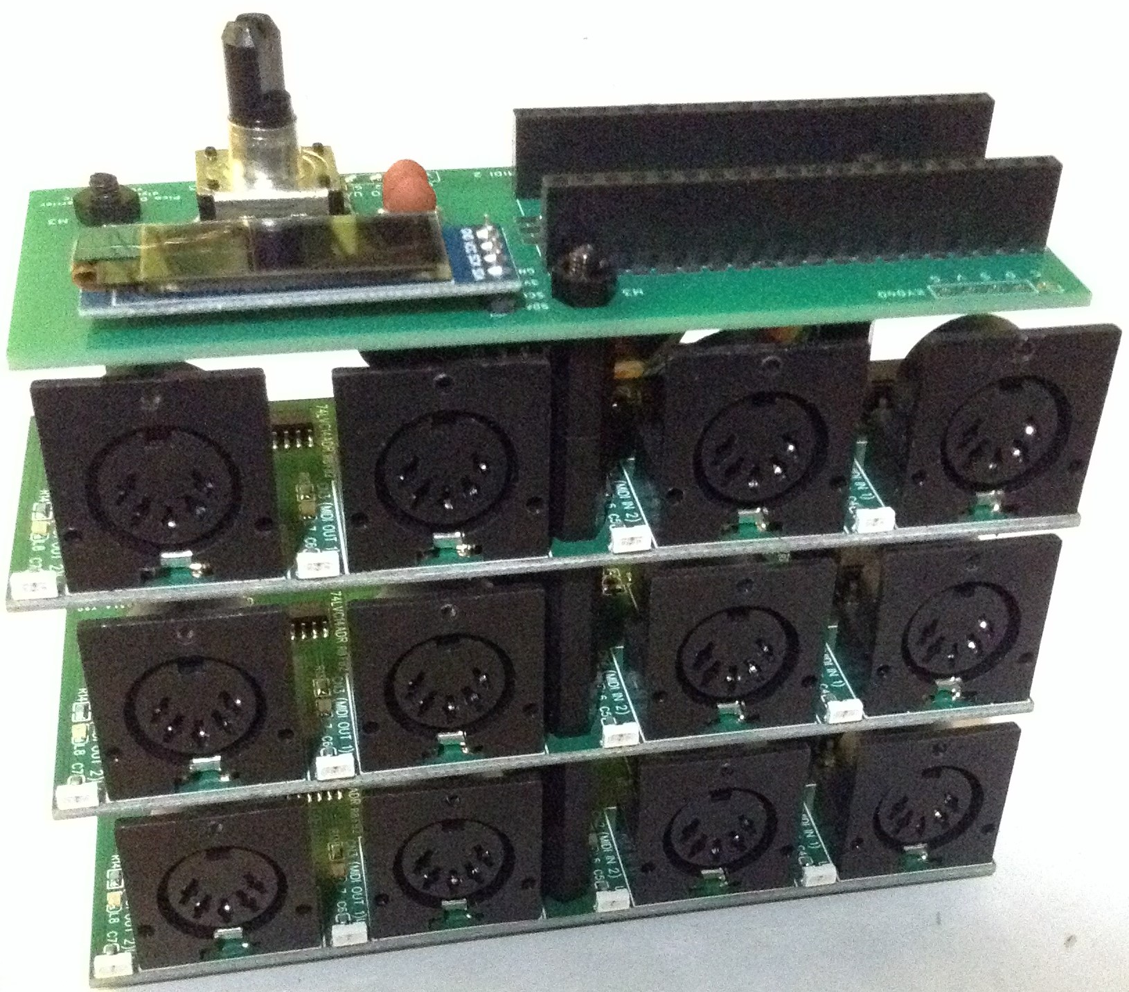
Here is a photo of the finished build.

Alternative build options:
- The SSD1306 could be left “off board” and mounted on a panel at right angles to the carrier.
- Instead of an on-board rotary encoder, there are connections for a KY040 rotary encoder module to be directly soldered onto the board.
- The Pico could be soldered directly onto the carrier board rather than using headers.
Assembly Instructions
These instructions apply to the use of the carrier with the aforementioned dual MIDI interface modules from VE7FIM.
Connecting cables are required. I cut the 20cm, 8-way Dupont-style cables into the following lengths (including the pin header sockets themselves):
- 70mm
- 80mm
- 120mm

Each MIDI module and the carrier are joined with three sets of two 12mm stand-offs joined together.
Note that it isn’t possible to get a nut on the top of the stand-off hole underneath the Pico. In fact, if the Pico is soldered directly to the board with no headers, then this hole will not be used at all.
I connected up my boards so that “MIDI 1” is the bottom board, “MIDI 2” in the middle, and “MIDI 3” at the top just beneath the carrier, simply because that seemed to be the easiest way to route the wires.

Testing
I recommend performing the general tests described here: PCBs.
PCB Errata
There should have been space for two pullup resistors on the I2C line giving the option to add them, in case the module being connected doesn’t have any. This would apply to both SDA and SCL. General “Internet wisdom” suggests a 4K7 resistor between each line and 3V3. If it is required then they can be hacked onto the I2C connector between SDA/SCL and the VCC pins.
If I redesigned the board, I might be tempted to “shift” the whole thing compared to the three holes to make it possible to fit a nut on to the hole under the Pico.
I still haven’t done anything with the LED connections yet either, so that is another future enhancement.
Closing Thoughts
This is a much more useful add-on to my original proto-board carrier. Now I have three MIDI interfaces available, I can work on some more sophisticated routing software.
These boards have been manufactured using the Seeed Fusion PCB service, which I am happy to continue to recommend. They have been supported with discount vouchers that I’ve been sent by Seeed for my previous projects.
Kevin

Sweet Rudabaker pie, that’s a delightful amount of PCB! 🙂
LikeLike