This is the build guide for my Raspberry Pi Pico MIDI Splitter.
If you are new to microcontrollers, see the Getting Started pages.

Bill of Materials
- Raspberry Pi Pico MIDI Splitter PCB (GitHub link below)
- Raspberry Pi Pico
- 1x H11L1 optoisolator
- 3x 74HCT14 (has to be the HCT version, not the HC version)
- 19x 220Ω resistors
- 1x 470Ω resistor
- 1x 1N914 or 1N4148 diode
- 4x 100uF ceramic capacitors
- 10x 5-pin 180 DIN sockets (see PCB and photos for footprints)
- Optional: 1x 6-pin DIP socket
- Optional: 3x 14-pin DIP sockets
- Optional: 2x 20-pin header sockets for the Pico

Build Notes
A straight forward “low to high” approach should be taken. Here is the recommended soldering order:
- Resistors and diode.
- 14 pin and 6 pin DIP sockets (if used).
- Capacitors.
- Pico 20-way headers (if used).
- DIN sockets.
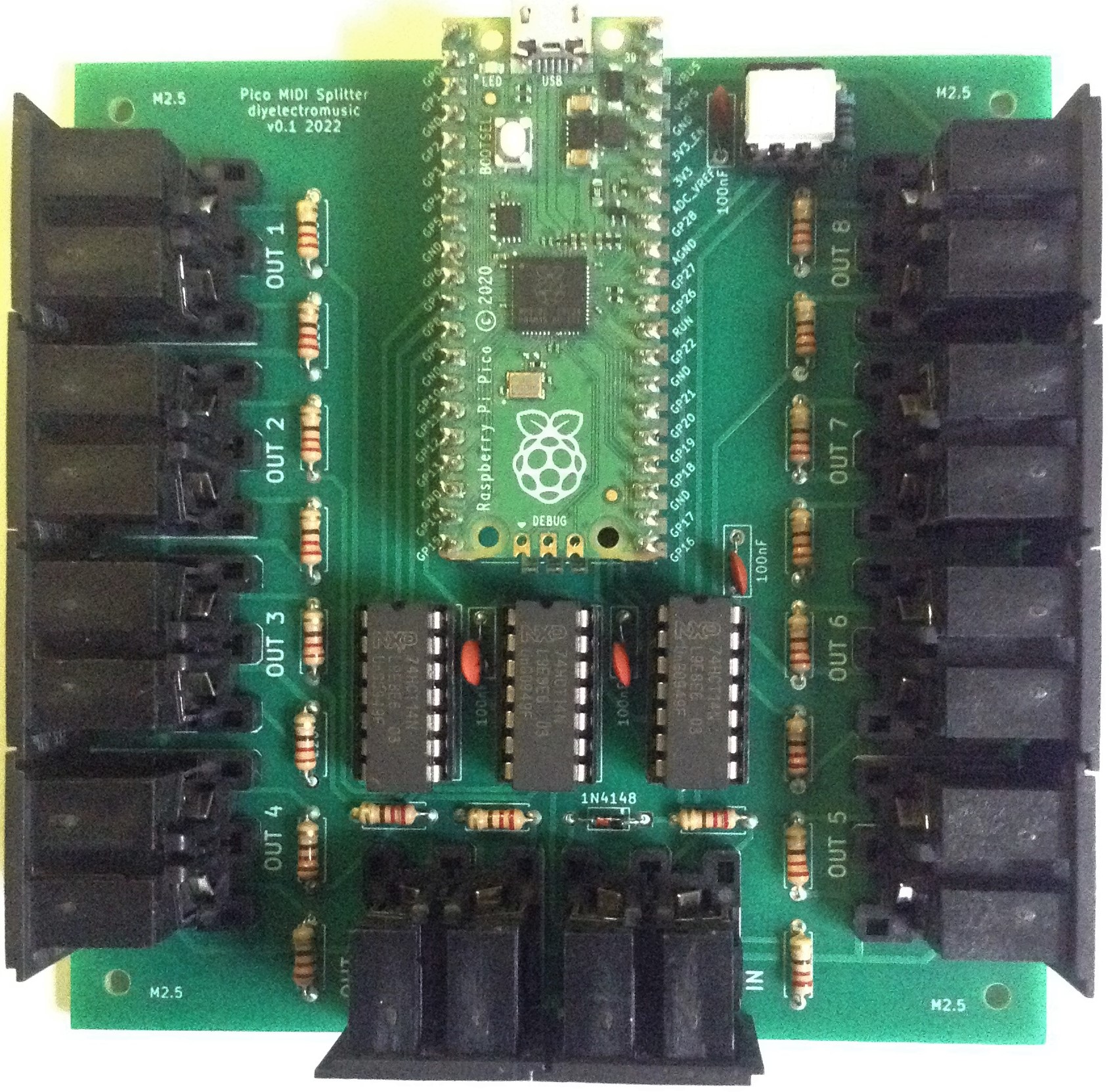
Here are some build progress photos.


Testing
I recommend performing the general tests described here: PCBs.
Applications
This will run the code from my Raspberry Pi Pico MIDI Channel Router directly, but it doesn’t make use of the UART connected MIDI OUT.
It can also be used with the code from my Raspberry Pi Pico Multi MIDI Router but with the number of RX UARTS set to zero. This is the configuration that provides 8 PIO output ports:
UART_BAUD = 31250
RX_PIN_BASE = 6
RX_NUM_UARTS = 0
TX_PIN_BASE = 6
TX_NUM_UARTS = 8 # Ports 2-9
HW_NUM_UARTS = 2 # Ports 0-1
PCB Errata
None at present.
In terms of enhancements, it might be useful to include some headers to break out the second UART port too.
Closing Thoughts
Many thanks to Seeed Fusion (as always) for the cost effective and speedy delivery of my boards.
Full disclosure: these boards were discounted using vouchers sent to me by Seeed following previous links from my posts. Otherwise, I have no specific links to Seeed or their service.
As always, it is possible I might have one or two spares, so feel free to get in touch if you want to.
Kevin

Got this working, except the midi out port right next to midi in.
Also, I’ve noticed that sustain pedal control change is ignored.
I wonder how to fix that 🙂
LikeLike
Not sure why just that port isn’t working, but iirc the two ports a the bottom are directly connected to RX/TX rather than PIO.
Don’t know why sustain is ignored, but I guess it depends what application you’re using, but assuming it is one of the Micropython scripts from me then they should be using my SimpleMIDIDecoder which (again iirc) has a default Thru function that should handle the routing for anything that isn’t NoteOn/NoteOff.
Either way you should be able to add some print statements in the Thru callback (I think they are there but commented out anyway) to see a little more what is going on.
Kevin
LikeLike