Here is the build guide for my Arduino MIDI Proto Shield.


Tutorials used in this project:
If you are new to microcontrollers, see the Getting Started pages.
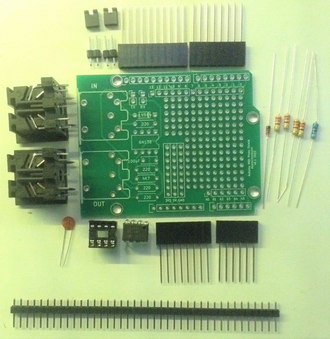
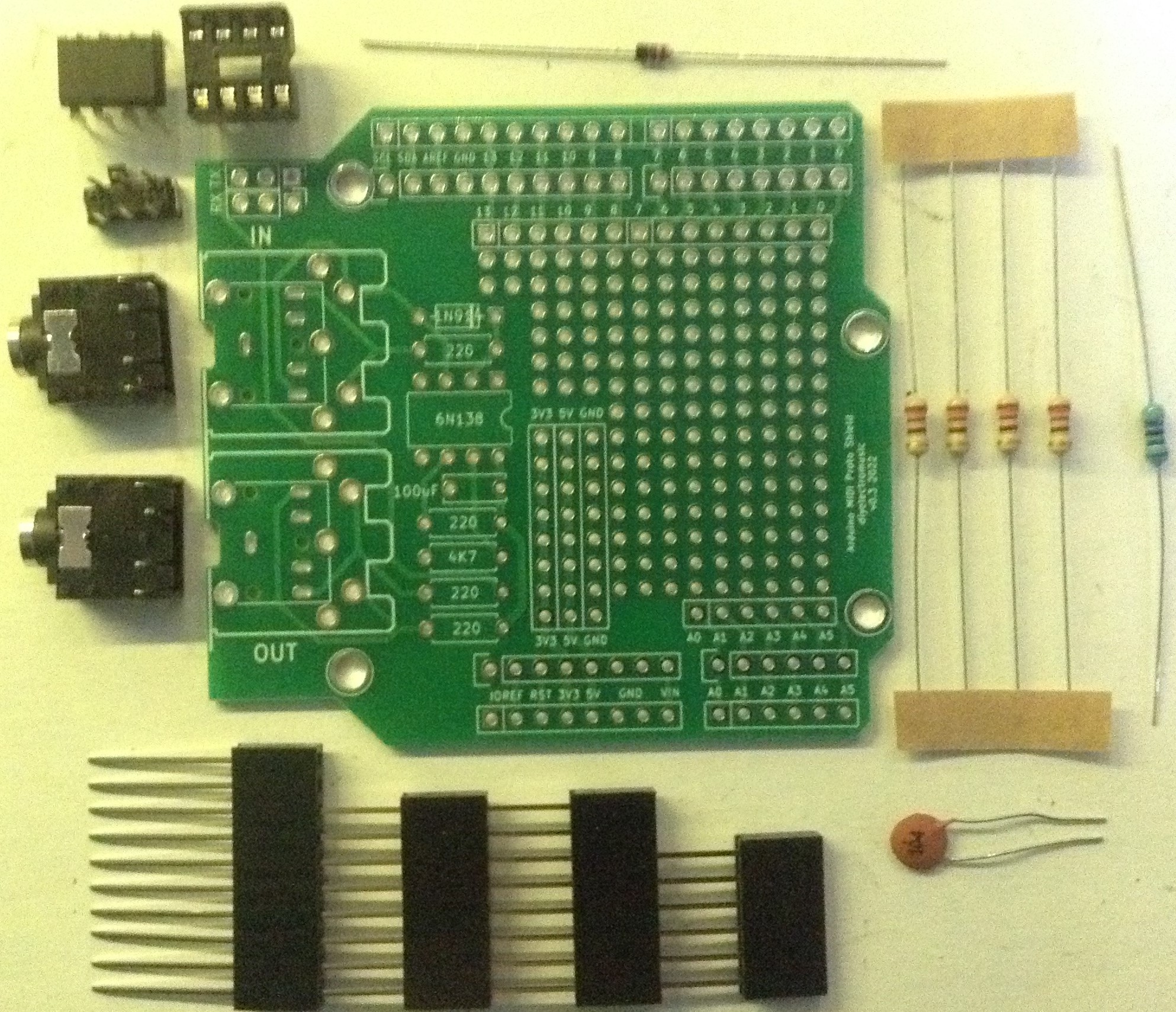
Bill of Materials
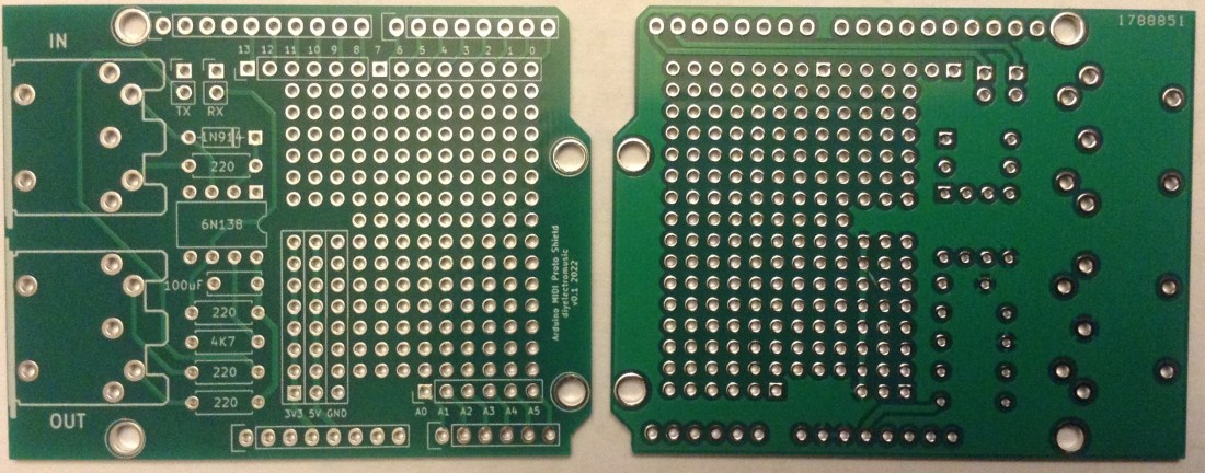
- The Arduino MIDI Proto Shield PCB (GitHub link below).
- 4x 220Ω resistors
- 1x 4K7Ω resistor
- 1N914 or 1N4148 diode or similar
- 100nF ceramic capacitor
- 6N138 optoisolator
- Optional: 8-pin DIP socket
- 2x 5-pin DIN sockets (pcb mount, see photos for footprint) OR
- Optional 2x TRS stereo jack sockets (pcb mount, see photos) – V2 only
- 2x 2-way header pins OR
- Optional: DPDT PCB mount switch (pcb mount, see photos) – V2 only
- 2x jumpers
- Arduino headers: 1×10 way, 2×8 way, 1×6 way (see note below).
For the Arduino headers you can use pins, sockets, extended pins, stacking headers, etc, it is really up to you.
But note that the MIDI IN socket WILL NOT fit with an original USB B socket Uno. It will end up shorting on the USB connector and won’t fit properly, so you’ll need extended pins on your headers or to use an Arduino Uno with a micro or mini USB socket.
The 8-pin DIP socket is optional but recommended. The jumpers and 2-way headers are there to allow the temporarily disabling of the MIDI link to the UART to allow sketches to be uploaded to the Arduino.
Update: V2 of this board includes the option to use two stereo TRS jack sockets for MIDI instead of DIN sockets, and the option for using a PCB mount DPDT switch instead of jumpers.
Build Steps
The build should proceed in a typical “low to high” component manner, with the following assembly order recommended:
- Start with the resistors and the diode.
- Then the 8-pin DIP socket (if used).
- Capacitor.
- 2-way jumpers.
- MIDI sockets.
- Arduino headers.
Here are some photos of the build in progress.

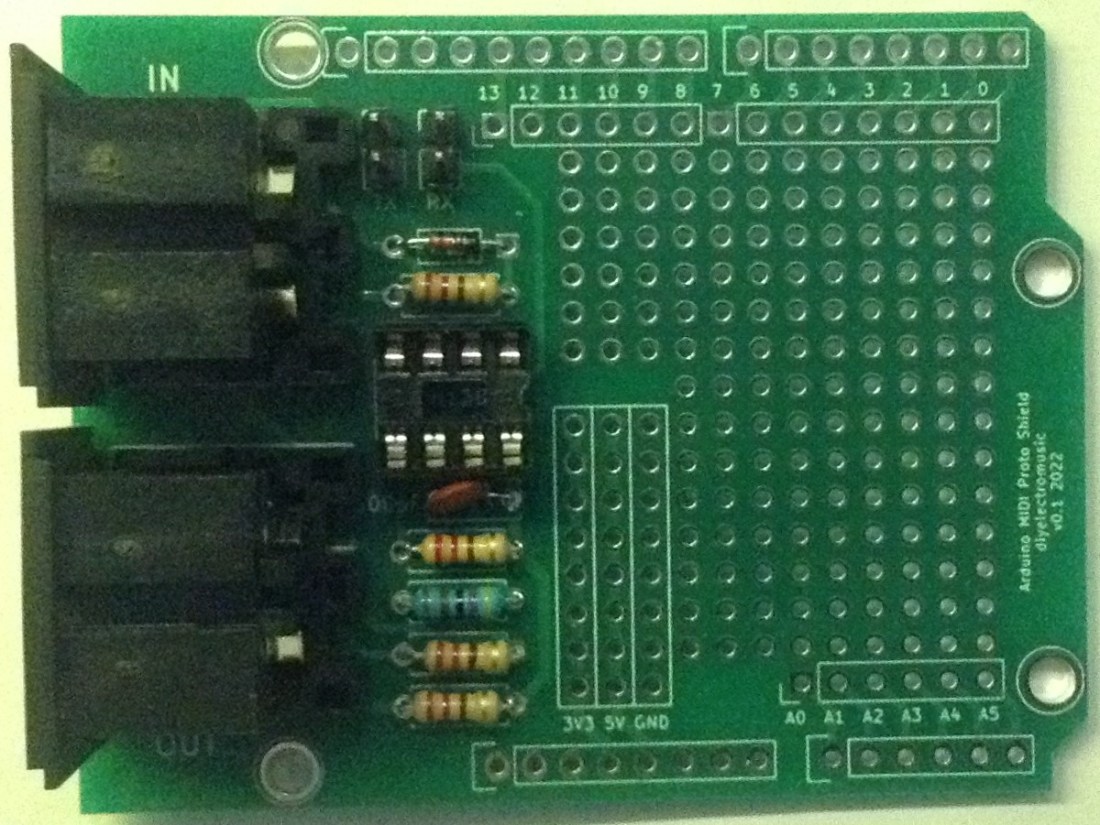

As already mentioned, the 2-way headers and jumpers allow the MIDI link to be disconnected from the UART to allow sketches to be uploaded to the Arduino.
In use, the MIDI is linked to D0/D1 with (as you’d expect):
- D0 (RX) = MIDI IN
- D1 (TX) = MIDI OUT
If one of the MIDI interfaces isn’t required that can be left unpopulated or just the jumper left off. The jumpers are labelled TX and RX.
The prototyping area has links to all IO pins D0 to D13, A0 to A6, even though D0 and D1 are connected to MIDI as already stated. It also has strips of holes for GND, 5V and 3V3.
The following Arduino header pins are not broken out to the prototyping area: VIN, SDA, SCL, RESET, AREF, although of course SDA/SCL are available on A4/A5 on an Uno.
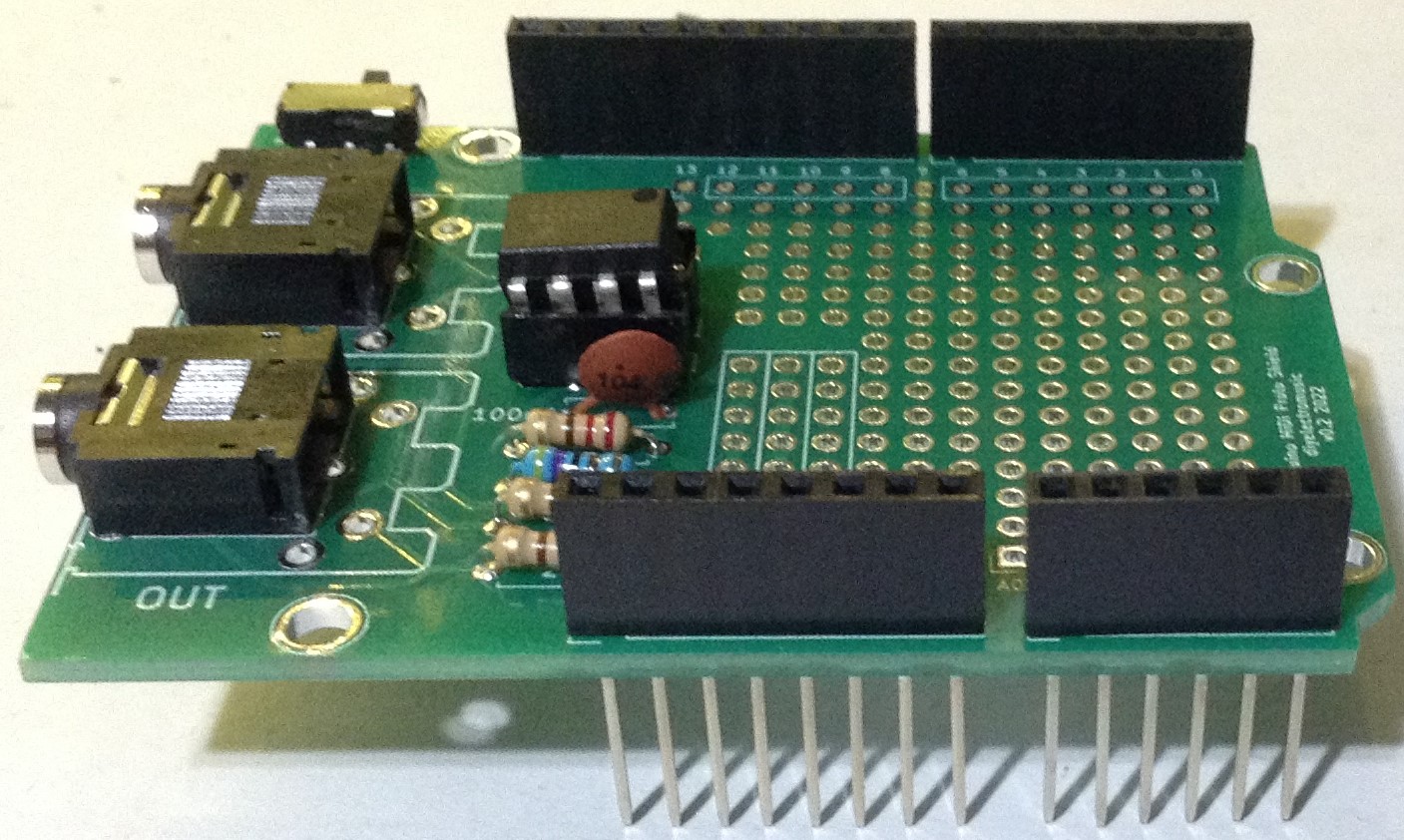
V2 Build Notes
The build process for V2 of the board is essentially the same as V1 but there is a choice of either 5 pin DIN sockets or PCB mount stereo TRS jack sockets. The TRS sockets support “Type A” (the MIDI standard) wiring.
Here are some photos highlighting a V2 build.

V3 Build Notes
The build process for V3 is the same as for V2. Once again there is the choice between DIN sockets or TRS (“Type A”) for MIDI.
Here are some photos highlighting a V3 build.


No additional headers have been added yet. The choice of additional headers for the extra IO pins can be either pins, sockets or right-angled or even left as unconnected pads to have wires soldered directly.
Testing
I recommend performing the general tests described here: PCBs.
PCB Errata
There is nothing specific to be aware of when using this board, but note that the MIDI OUT stage is just a very simple, unbuffered output circuit. For the V1, I might change the supporting connector pads on the DIN sockets to rectangles, but this isn’t really possible on the V2 or V3 boards.
Possible enhancements in the future might include:
- Breaking out SDA/SCL explicitly within the prototyping area.
- A MIDI activity LED.
- A proper buffered MIDI OUT stage.
V2 and V3 also include:
- The option of a switch rather than jumpers to disable the MIDI link.
- A combined MIDI DIN and TRS (“Type A”) footprint for the sockets (like the Adafruit MIDI Feather Wing).
You can find the PCB design files on GitHub here: https://github.com/diyelectromusic/sdemp_pcbs/tree/main/ArduinoMIDIProtoShield
Closing Thoughts
Many of my projects have involved adding some hardware or components to an Arduino and then connecting it up to a MIDI interface. I can see it being really useful to have a shield with the MIDI interface section pre-built and am now tempted to put a couple of them together, so they are ready to go.
V2 makes the board much more stackable – basically embedded the ideas from Arduino Stackable TRS MIDI Interface into the PCB itself. V3 makes the spare IO on the stackable board more available. I was particularly thinking about its potential use with the Arduino Synth Shield.
These boards have been manufactured using the Seeed Fusion PCB service, which I am happy to continue to recommend. They have been supported with discount vouchers that I’ve been sent by Seeed for my previous projects.
As always, it is possible I might have one or two spares, so feel free to get in touch if you want to.
Kevin
