Here is the build guide for my Raspberry Pi Pico MIDI Proto Expander.

Warning! I strongly recommend using old or second hand equipment for your experiments. I am not responsible for any damage to expensive instruments!
These are the key tutorials for the main concepts used in this project:
- PCB Design in KiCad from Arduino Uno Dual Merge MIDI “Shield” – Part 2.
- Ordering your PCB: a Beginners Guide for Manufacturer Options
If you are new to microcontrollers, see the Getting Started pages.
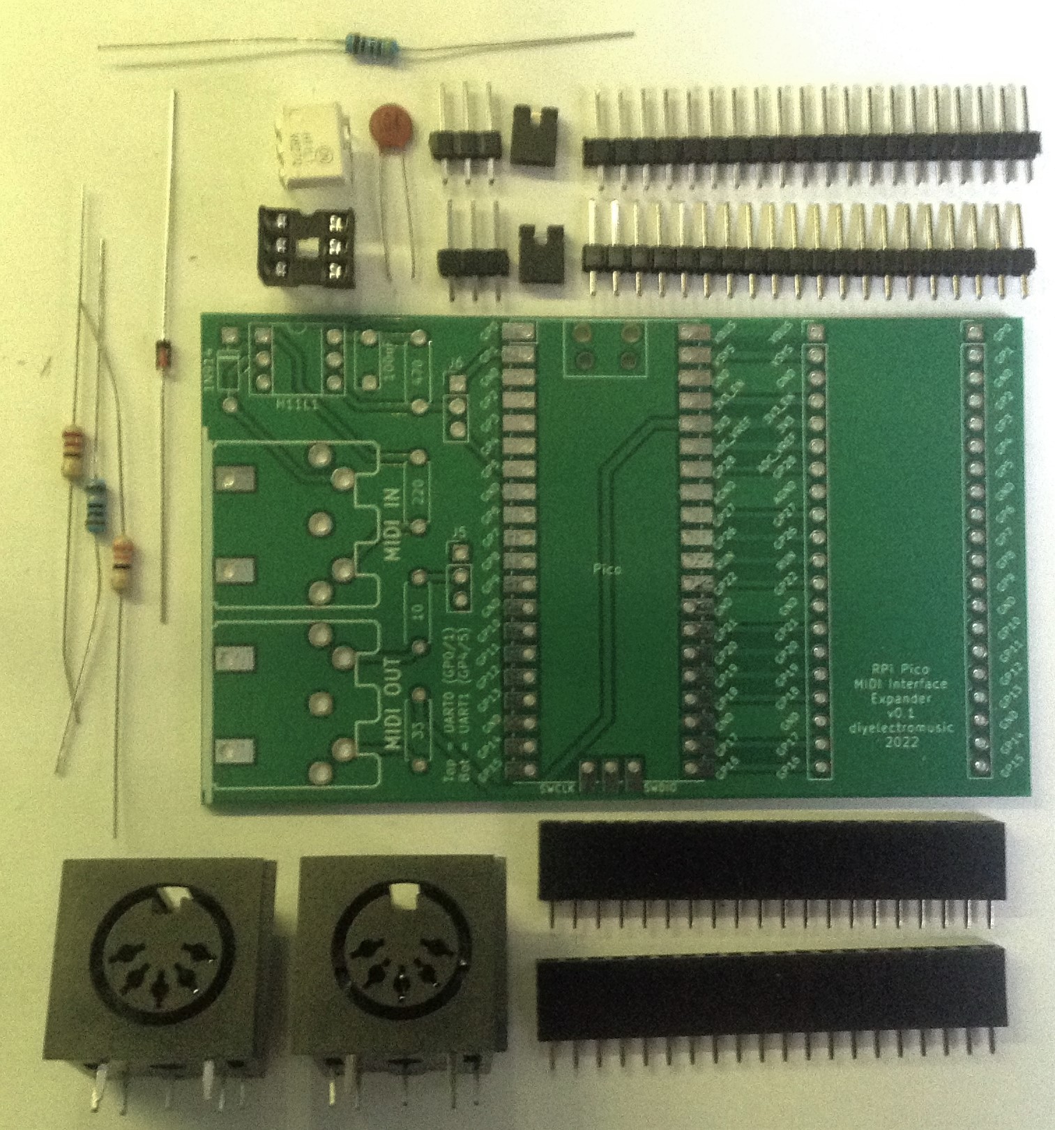
Bill of Materials
- Naturally, you’ll need a Raspberry Pi Pico MIDI Proto Expander PCB (GitHub link below).
- Resistors: one each of 220Ω, 470Ω, 10Ω, 33Ω.
- 100nF ceramic capacitor (not 100uF as it says on the PCB).
- 1N914 or 1N4148 diode or similar.
- H11L1 optoisolator.
- 2x 5-pin 180 DIN sockets (see photos for footprint).
- Optional: 6 pin DIP socket.
- 2x jumpers.
- 2x 3-way header pins.
- 2x 20-way header pins.
- Optional: 2x 20-way header sockets for the Raspberry Pi Pico.
The sockets are optional but highly recommended.
Build Steps
The build should be a relatively straightforward through-hole components build. All components should be placed on the same side of the board, as indicated by the markings.
I recommend the following order:
- Diode and resistors.
- 6-way DIP socket (if used).
- Capacitor.
- 20-way header sockets (if used).
- 3-way pin headers. Alternatively, if you don’t need to choose between UART 0 and UART 1 you could directly hard-wire the appropriate links rather than use headers and jumpers.
- 20-way pin headers.
- H11L1 if soldered directly.
- 5-way DIN sockets.
At this point it is worth doing some basic testing – continuity and ensuring there are now shorts between power and ground and so on. Then finally add the jumpers, H11L1 and plug in your Raspberry Pi Pico.
Here are some of the build steps in photos.


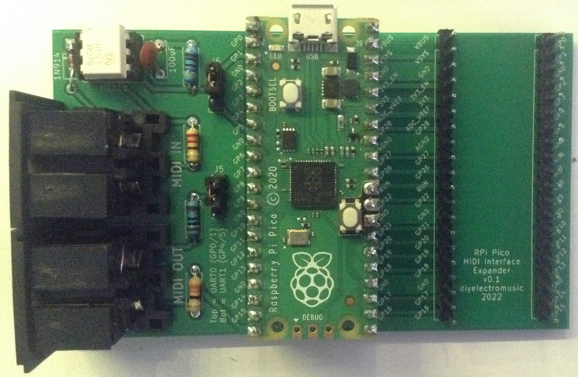
The MIDI interface can be hooked up to either UART 0 or UART 1 depending on the jumper settings. In the above photo you can see the jumpers set for UART 0 on GP0 and GP1. Switch them both over to the lower two pins to change to UART 1 on GP4 and GP5.
In principle, the two jumper settings don’t need to match. There is nothing stopping the board being configured with one MIDI port on UART 0 and one on UART 1 if that is useful.
Testing
I recommend performing the general tests described here: PCBs.
PCB Errata
As far as I’m aware at the time of writing, there is just two silkscreen errors:
- The capacitor is mislabeled as 100uF – it should be 100nF.
- The two 3-way pin headers are labelled J5 and J6. They could have a more useful label!
Potential Future Enhancements:
- A future version could include some mounting holes (I did think about it, but then decided not to).
- A MIDI activity LED might be useful in the future.
- The two 3-way pin headers to select the UART could be replaced with a switch.
- I am wondering about another version with two or more expansion spots.
You can find the PCB design files on GitHub here: https://github.com/diyelectromusic/sdemp_pcbs/tree/main/PicoMIDIProto
Closing Thoughts
As I mentioned last time, I’ve been using the Seeed Fusion pcb service, and spending my discount vouchers and I’m very happy to keep doing so. I have a couple more boards on the way back to me that supported by the last of this batch of vouchers.
Also, as always I have a couple of unpopulated pcbs spare if anyone is interested in having one. Just ping me a message via some suitable route. Alternatively, all the required design files are on GitHub.
Kevin

One thought on “Raspberry Pi Pico MIDI Proto Expander – Part 2”