This is the set of build notes for the larger of my MiniDexed Raspberry Pi IO Boards.

Warning! I strongly recommend using old or second hand equipment for your experiments. I am not responsible for any damage to expensive instruments!
These are the key tutorials for the main concepts used in this project:
- My first experiments in KiCad: Arduino Uno Dual Merge MIDI “Shield” – Part 2
- MiniDexed: “Bare Metal” Raspberry Pi MiniDexed DX7
If you are new to microcontrollers and single board computers, see the Getting Started pages.
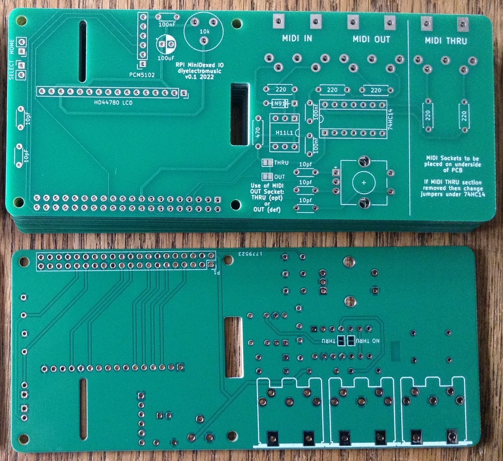
Bill of Materials
- Raspberry Pi 3 or 4 with associated power, uSD card, etc.
- You’ll need the larger (HD44780) version) of the PCB: MiniDexed Raspberry Pi IO Board (GitHub link below).
- 1x 16×2 directly connected (i.e. not the I2C version) HD44780 LCD display (see photos). Note: this PCB assumes a 5V version of the LDC module.
- 1x GY-PCM5102 module (see photos).
- 1x H11L1 optoisolator.
- 1x 74HCT14 hex inverters (has to be the HCT version, not the HC version even though it says “HC” on the PCB!).
- 5x 220O resistors.
- 1x 470O resistor.
- 1x 10K trim pot (see photos).
- 1x 1N914 or 1N4148 signal diode.
- 3x 100nF ceramic disk capacitors.
- 5x 10nF ceramic disk capacitors (not 10pF as stated on the PCB).
- 1x 100uF electrolytic (16V)
- 1x rotary encoder with switch (see photos).
- 3x 5-pin 180 DIN PCB mounted sockets (see photos).
- 2x 2-way header pins – optional.
- 1x 6-way DIP socket – optional.
- 1x 14-way DIP socket – optional.
- 1x extended 2×20-way GPIO header socket for the Raspberry Pi.
- 1x 6-way header socket – optional (for PCM5102).
- 1x 16-way header socket – optional (for 16×2 LCD).
As always, a socket is recommended for the H11L1 and 74HCT14, and the PCM5102 and LCD modules can either be used with sockets or soldered directly, depending on how brave (or lucky?) you’re feeling.
Note the LCD might need to be raised to ensure it fits over the H11L1, especially if the H11L1 is in a socket of its own, and a header socket is probably the easiest way to do this.
Build Steps
This should be a relatively straight forward “through hole components” build. I did things in the following order:
- Resistors and diode.
- DIP sockets.
- Capacitors.
- Trim pot
- If you are using headers for the PCM5102 and LCD then do them next.
- If you are using header pins for the switches, do them next.
- MIDI sockets (note these go on the underside of the board).
- Rotary Encoder.
- PCM5102 (if you aren’t using headers) – WARNING: see note below about the PCM5102 solder bridges before soldering.
- GPIO socket. Note: extension spacers might be required (see photos below).
- H11L1 and 74HCT14 (if you aren’t using sockets).
- LCD (if you aren’t using headers). Note that you will have to ensure it clears the other components, especially the H11L1, so it might need extending somehow.
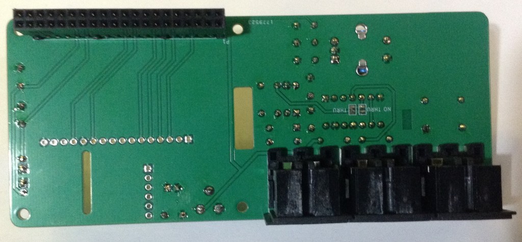
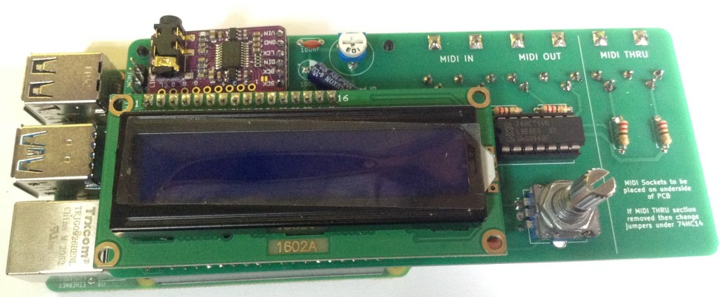
Note that an extended GPIO header is required to give the board a little extra clearance from the Raspberry Pi and to allow for the MIDI sockets to fit on the underside of the board. But you will have to trim off excess pin lengths to allow the LCD to fit over the top.

Additional spacers might be required on the extended GPIO header to ensure the PCB is lifted above the Pi enough to allow for the MIDI sockets to be fitted. I used the plastic spacers off a row of normal header pins.

Recall that the GPIO headers and MIDI sockets go on the underside of the board.
PCM5102 configuration:
The GY-PCM5102 modules I’m using, as shown in the photos, as the same as used for the Clumsy MIDI project and you have to be sure the configuration jumpers on the back of the modules are correctly set up before soldering in place. Full details of what is required can be found on the Clumsy MIDI pages here (see the important note about the “DAC solder bridges”): https://github.com/gmcn42/clumsyMIDI.
Testing
I recommend performing the general tests described here: PCBs.
I used the “fishing wire trick” to be able to plug in the PCM5102 without soldering and requiring using headers (nylon fishing wire in the holes gives enough traction to be able to push a header pin in, have it grip and make contact, without soldering). This allowed me to check everything was working, including the modules, whilst still giving me options for debugging.
It is probably also worth attempting to power up the board without connecting it to the Raspberry Pi as a “smoke test”. The PCM5102 and LCD are powered from the 5V line, whilst the H11L1 is powered from the 3V3 line.
Once everything seems working, the trim pot can be used to adjust the contrast for the LCD, so if you don’t see anything on the LCD then try adjusting this.
PCB Options
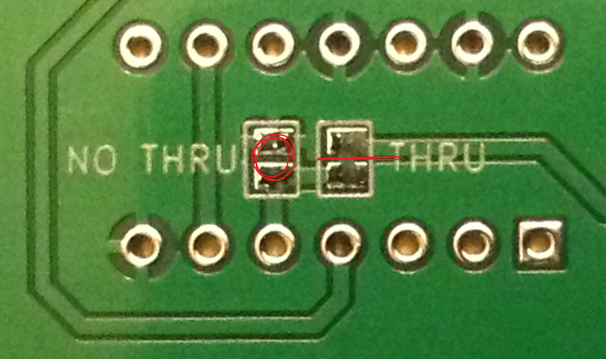
The PCB as shown above includes MIDI IN, OUT and THRU ports. It is possible to take a hacksaw and cut off the last portion of the PCB to remove the third MIDI port. If you do this, then there are some solder bridges that need to be changed on the underside of the board. These will remove the link from RX into the inverters used for the THRU socket and alternatively connect those inputs to GND.
The following photo shows where the bridge has to be cut and where the new bridge should be made.
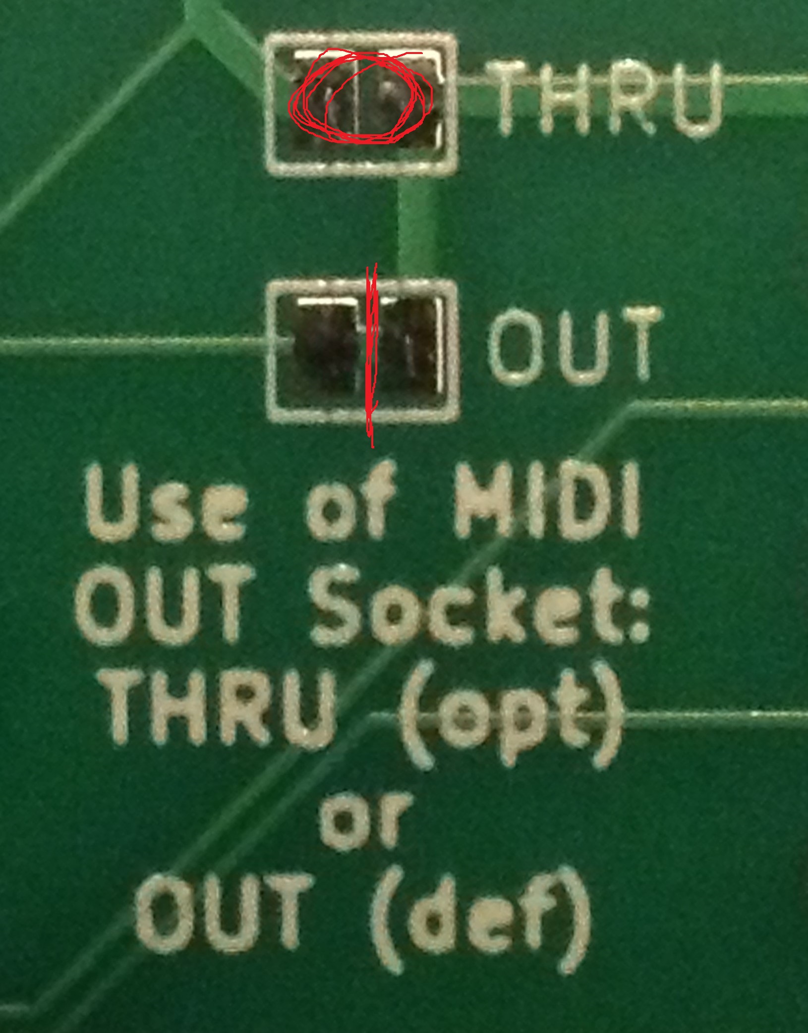
Once the third MIDI port has been removed, then there is an additional option for the MIDI OUT port. It can be configured as a MIDI THRU instead. of OUT
In fact this option is available regardless of whether there is a third MIDI port or not – if this is changed whist keeping the third MIDI port, then the board will have one-IN and two-THRU ports.
Again the photo below shows where this needs cutting to break the default (MIDI OUT is a genuine OUT) and re-soldering to change the mode (MIDI OUT becomes a MIDI THRU).
Note that these bridges will end up underneath the LCD so this has to be decided prior to soldering on the LCD if headers aren’t being used.
PCB Errata
Functionally, all seems ok, but there are a couple of markings I’d change.
- First off, an error in the capacitor values – the debouncing capacitors should be 10nF not 10pF.
- The IC is a 74HCT14 not a 74HC14 as labelled on the board.
- I labelled the switch connectors Home and Select, but given the flexibility in the configuration (and the fact that typically the encoder’s switch will be “select), maybe they should just be “button 1” and “button 2”.
- The diode is labelled 1N914 but I believe 1N9148 tend to be preferred?
In terms of potential enhancements, the following might be worth considering:
- There are no mounting holes for the LCD.
- The LCD needs enough clearance to sit above the H11L1. This means using a header, but it might be possible to re-arrange things slightly to allow its use without.
- It might be useful to support either 5V or 3V3 LCD modules.
You can find the PCB design files on GitHub here: https://github.com/diyelectromusic/sdemp_pcbs/tree/main/RpiMiniDexedHD44780
MiniDexed Configuration
I’m not going through how you set up and run MiniDexed. My own notes on it can be found here: “Bare Metal” Raspberry Pi MiniDexed DX7.
The following settings are required in the minidexed.ini file (correct as of time of writing, but the MiniDexed project shifts pretty quickly!). Note that these GPIO pin settings are quite different to the default MiniDexed setup!
For the HD44780 LCD:
LCDEnabled=1
LCDPinEnable=10
LCDPinRegisterSelect=9
LCDPinReadWrite=0
LCDPinData4=22
LCDPinData5=27
LCDPinData6=17
LCDPinData7=4
LCDI2CAddress=0x00
SSD1306LCDI2CAddress=0
LCDColumns=16
LCDRows=2
For the Rotary Encoder:
EncoderEnabled=1
EncoderPinClock=24
EncoderPinData=23
For the two buttons, and the rotary encoder switch itself:
ButtonPinBack=5
ButtonActionBack=click
ButtonPinSelect=25
ButtonActionSelect=click
ButtonPinHome=6
ButtonActionHome=click
ButtonPinShortcut=25
If you don’t want to use the buttons, but would rather use the button on the rotary encoder for everything, then I suggest (which is the default, at the time of writing):
ButtonPinBack=25
ButtonActionBack=longpress
ButtonPinSelect=25
ButtonActionSelect=click
ButtonPinHome=25
ButtonActionHome=doubleclick
ButtonPinShortcut=25
Closing Thoughts
The main idea for this build was to have all of the main connections (apart from the Pi’s USB ports) at the back, so there is a good possibility that this could be put in a case. As described above there are one or two things that could still be improved, but I’m quite pleased with this first effort.
Disclaimer: Once again, I used the Seeed Fusion service as I had some discount coupons I’d been sent, and once again I have absolutely no complaints about their quick, cheap service. I’m very pleased with these boards.
I am in no way connected to or affiliated with Seeed, but if they (or any other manufacturer for that matter) want to send me discounts, I for one am very happy to receive them.
Either way I’ll always post things here as I see them and make it clear when I’ve taken advantage of any special offers or vouchers.
Kevin

This is excellent work, really.
Do you by any chance have a schematic you’d be willing to publish? Your board covers every element (save for a third button) I’m hoping to integrate with my minidexed synth, though I’m trying to do it offboard in a tea tin. These days I’m so scattered though, and ruining a Pi is not as cost effective as it used to be, so a solid reference schematic would be a real joy.
LikeLike
Hi there. Hopefully everything is in the linked post with the “design” information for the boards. See: https://diyelectromusic.wordpress.com/2022/07/28/minidexed-raspberry-pi-io-board/
It should also be in the Github link too. But do note the provisos about my level of electronics (in)expertise 🙂
Do let me know what you get up to. Good luck!
Kevin
LikeLike
Hi Kevin,
I’m Douglas, I’m Brazilian and I found your site while searching for information about a project using Minidexed.
I have a Yamaha DX9 keyboard, which is the less expensive version of the iconic DX7. While searching for a DX7, I stumbled upon this DX9. It wasn’t working; I partially restored it. Now it powers on and functions as a MIDI controller, but unfortunately it no longer reproduces the original DX9 sounds. However, since it works as a controller, I’ve already tested it with Minidexed on my PC and the DX7 sounds sound great playing on the DX9.
That’s why I’m interested in the Minidexed. I want to incorporate the Raspberry Pi 3B I have available into the DX9, internally connect the DX9’s MIDI out to the Raspberry Pi’s MIDI in to control the Minidexed, have an encoder to choose presets with buttons, and have the DX9’s display show the text.
The DX9’s display is a standard Arduino 16×2, both I2C and parallel, and I already have the display updated for this. Looking at your beautiful project, I’m unsure which model and version of board to build. I can redesign and manufacture the board here at home, but which model do you recommend for use with my standard 16×2 LCD? Version 1? If you understood correctly, I will fully embed the Minidexed inside the DX9 and use the DX9 as a DX7 on stage and in my studio.
Congratulations on the beautiful project. If you want to discuss more projects, you can contact me at douglas.baroni@outlook.com.
“May the force be with you!”
LikeLike
Yes, I only have one version of the PCB that supports the parallel-connected 16×2 LCD, but if you are using the I2C backpack type of 16×2 LCD, then you could get away with using the OLED version but wire it up to the I2C 16×2 instead. It won’t be as neat as the 16×2 is a lot bigger than a ssd1306, but it would work.
To be honest, if everything is internal to the DX9 anyway, you probably don’t really need a PCB, you could solder/connect wires directly to the Pi. Or at least you could get away with a lot less, depending on what you need connecting to what. See the Zero versions of my PCBs for some ideas.
In fact, I have a few different versions of the PCBs now, so it is worth looking through them all and seeing which might work best for you. I’ve added them all to the list of hardware projects on the miniDexed wiki if you want to scan them quickly, or see the “pcbs” link at the top of my blog.
Note: there is a V2 of the OLED version of this board now too that supports MIDI TRS sockets in addition to DIN.
Good luck!
Kevin
LikeLike