This is the set of build notes for the smaller of my MiniDexed Raspberry Pi IO Boards.
- Update: There is a newer version of this board: MiniDexed Raspberry Pi IO Board V2 Design.
Warning! I strongly recommend using old or second hand equipment for your experiments. I am not responsible for any damage to expensive instruments!
These are the key tutorials for the main concepts used in this project:
- My first experiments in KiCad: Arduino Uno Dual Merge MIDI “Shield” – Part 2
- MiniDexed: “Bare Metal” Raspberry Pi MiniDexed DX7
If you are new to microcontrollers and single board computers, see the Getting Started pages.

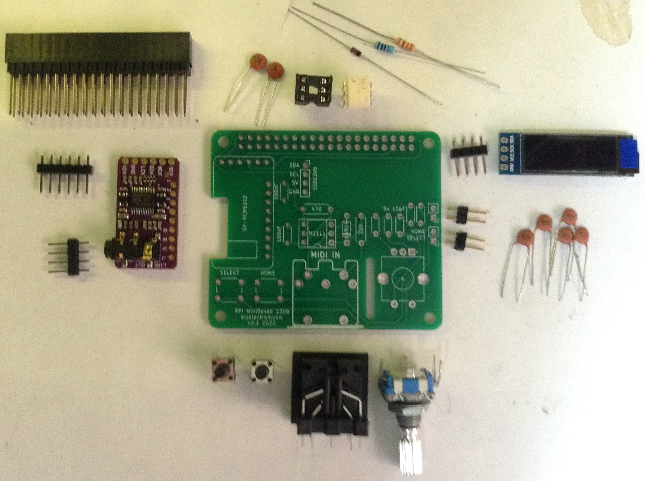
Bill of Materials
- Raspberry Pi 3 or 4 with associated power, uSD card, etc.
- You’ll need the smaller (SSD1306 version) of the PCB: MiniDexed Raspberry Pi IO Board (GitHub link below).
- 1x 128×32 I2C OLED SSD1306 display (see photos). Note it requires the pinout SDA-SCL-5V-GND. WARNING: Similar looking modules have been seen with different variations of this! Also, ensure it has built-in level shifting for 3V3 I2C operation.
- 1x GY-PCM5102 module (see photos).
- 1x H11L1 optoisolator.
- 1x 220Ω resistor.
- 1x 470Ω resistor.
- 1x 1N914 or 1N4148 signal diode.
- 2x 100nF ceramic disk capacitors.
- 5x 10nF ceramic disk capacitors (not 10pF as stated on the PCB).
- 1x rotary encoder with switch (see photos).
- 1x 5-pin 180 DIN PCB mounted socket (see photos).
- 2x “button” push-switches (see photos) – optional.
- 2x 2-way header pins – optional.
- 1x 6-way DIP socket – optional.
- 1x extended 2×20-way GPIO header socket for the Raspberry Pi.
- 1x 4-way header socket – optional.
- 1x 6-way header socket – optional.
As always, a socket are recommended for the H11L1, and the SSD1306 and PCM5102 modules can either be used with sockets or soldered directly, depending on how brave (or lucky?) you’re feeling.
Build Steps
This should be a relatively straight forward “through hole components” build. I did things in the following order:
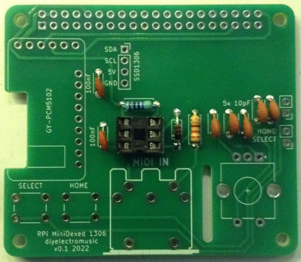
- Resistors and diode.
- 6-pin DIP socket.
- Capacitors.
- Buttons (if used).
- If you are using headers for the SSD1306 and PCM5102 then do them next.
- If you are using header pins for the switches, do them next.
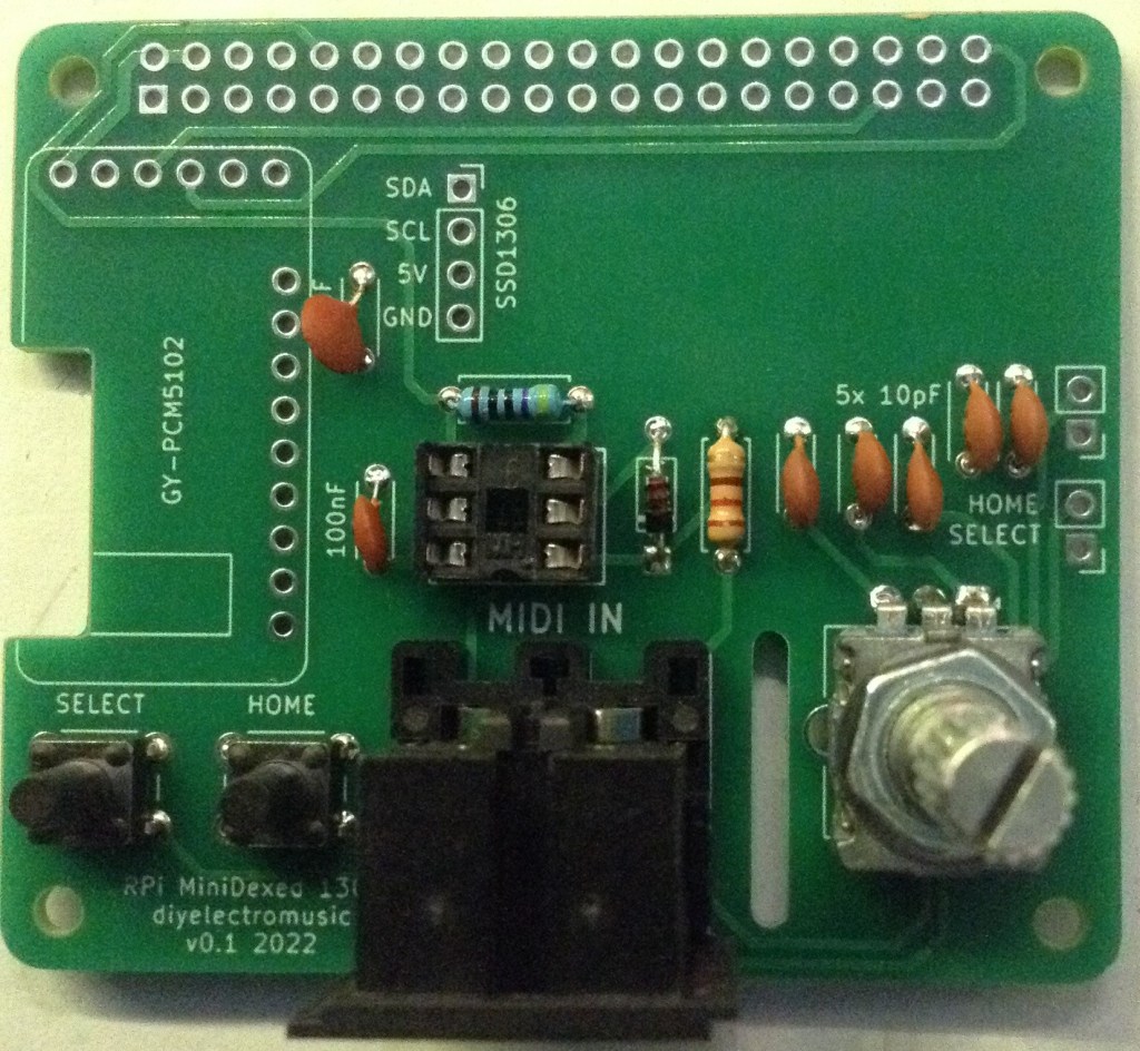
- MIDI socket.
- Rotary Encoder.
- PCM5102 and SSD1306 (if you aren’t using headers) – WARNING: see note below about the PCM5102 solder bridges before soldering.
- GPIO socket.
Note that an extended GPIO header is recommended to give the board a little extra clearance from the Raspberry Pi, but it means that if you don’t want the extra pins above the board, they should be cut off once soldered in place.
PCM5102 configuration:
The GY-PCM5102 modules I’m using, as shown in the photos, as the same as used for the Clumsy MIDI project and you have to be sure the configuration jumpers on the back of the modules are correctly set up before soldering in place. Full details of what is required can be found on the Clumsy MIDI pages here (see the important note about the “DAC solder bridges”): https://github.com/gmcn42/clumsyMIDI.
SSD1306 OLED Logic Levels
Several versions of these modules exist, but to use it with a Raspberry Pi requires one with 3V3 level shifters included. The 128×32 variety used in the photos often seems to include these, but the 128×64 variety often won’t!
The level shifters can be spotted on the back as follows:

In this case, marked “U2”. But to be sure, power the unit from 5V and measure the voltage on the SCL and SDA pins to see if it is pulled up to 3V3 or 5V.
Testing
I recommend performing the general tests described here: PCBs.
I used the “fishing wire trick” to be able to plug in the SSD1306 and PCM5102 without soldering and require using headers (nylon fishing wire in the holes gives enough traction to be able to push a header pin in, have it grip and make contact, without soldering. This allowed me to check everything was working, including the modules, whilst still giving me options for debugging.
It is probably also worth attempting to power up the board without connecting it to the Raspberry Pi as a “smoke test”. The PCM5102 and SSD1306 are powered from the 5V line, whilst the H11L1 is powered from the 3V3 line.
PCB Errata
Functionally, all seems ok, but there are a couple of markings I’d change.
- First off, an error in the capacitor values – the debouncing capacitors should be 10nF not 10pF.
- I labelled the switches Home and Select, but given the flexibility in the configuration (and the fact that typically the encoder’s switch will be “select), maybe they should just be “button 1” and “button 2”.
- The diode is labelled 1N914 but I believe 1N9148 tend to be preferred?
- I suspect I ought to use better capacitors (I know the Clumsy MIDI board recommends “X7R or film (e.g. WIMA MKS2)”).
- It might be worth adding a larger capacitor for the power to the board in general.
You can find the PCB design files on GitHub here: https://github.com/diyelectromusic/sdemp_pcbs/tree/main/RpiMiniDexedSSD1306
MiniDexed Configuration
I’m not going through how you set up and run MiniDexed. My own notes on it can be found here: “Bare Metal” Raspberry Pi MiniDexed DX7.
The following settings are required in the minidexed.ini file (correct as of time of writing, but the MiniDexed project shifts pretty quickly!).
For the SSD1306 LCD:
SSD1306LCDI2CAddress=0x3C
SSD1306LCDWidth=128
SSD1306LCDHeight=32
LCDColumns=20
LCDRows=2
For the Rotary Encoder:
EncoderEnabled=1
EncoderPinClock=10
EncoderPinData=9
For the two buttons, and the rotary encoder switch itself:
ButtonPinBack=5
ButtonActionBack=click
ButtonPinSelect=11
ButtonActionSelect=click
ButtonPinHome=6
ButtonActionHome=click
ButtonPinShortcut=11
If you don’t want to use the buttons, but would rather use the button on the rotary encoder for everything, then I suggest (which is the default, at the time of writing):
ButtonPinBack=11
ButtonActionBack=longpress
ButtonPinSelect=11
ButtonActionSelect=click
ButtonPinHome=11
ButtonActionHome=doubleclick
ButtonPinShortcut=11
Closing Thoughts
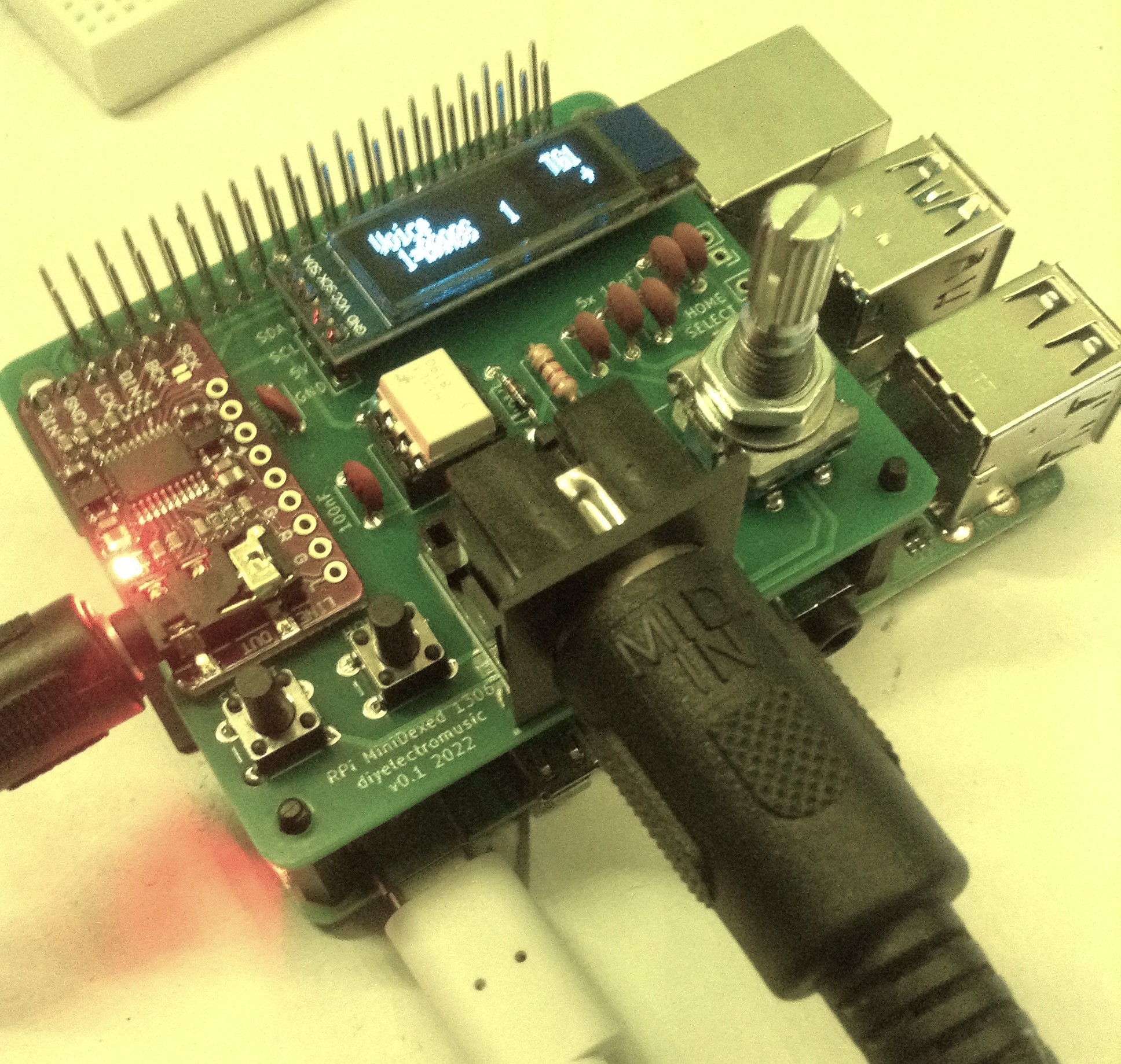
I love the idea that all I need is power, an audio output and a MIDI link (either USB or serial) and I have eight DX7s on hand and ready to go in this small, neat unit!
This one doesn’t really lend itself to being put in a case, although I guess it could if you extended the link to the display and buttons. But my next build, using the larger of the two PCBs, hopefully will!
As always, I have a small number of prototype boards, so if you might be interested in having a go yourself, ping me a private message somehow and we can talk.
Disclaimer: Once again, I used the Seeed Fusion service as I had some discount coupons I’d been sent, and once again I have absolutely no complaints about their quick, cheap service. I’m very pleased with these boards.
I am in no way connected to or affiliated with Seeed, but if they (or any other manufacturer for that matter) want to send me discounts, I for one am very happy to receive them.
Either way I’ll always post things here as I see them and make it clear when I’ve taken advantage of any special offers or vouchers.
Kevin

Hi, Kevin,
Fresh off of a success with your Arduino MIDI Proto Shield I thought I’d try making your MiniDexed Raspberry Pi IO Board (the one with the ssd1306). I haven’t had luck with it, however. There seems to either be something missing from one of the Gerber files, a Gerber file is missing, or, in my ignorance, I’m doing something wrong…in any case, the PCB manufacturer reports an error when I upload the Gerber files. As a test, I tried uploading the clumsy midi files, and that worked without a hitch (the same was true for the proto shield files). Can you help?
Thanks,
Peter
LikeLike
Sorry, I’m not sure what is going wrong, but I’ve just zipped up the directory from GitHub (there are 9 files to ZIP with no path information) and it has uploaded fine to Seeed Fusion, PCBWay and JLCPCB…
Any clue as to what it is complaining about? Who are you using to make it?
Kevin
LikeLike
Thanks for your reply. I downloaded the 9 files, put them in a folder, zipped it, and attempted to upload it to each of the three services you listed. JLCPCB, for example, says “Can not identify the board outline” when I open the Gerber viewer. I notice also that the board’s dimensions aren’t filled in. Speed Fusion says “Drill file not found…; Outline not found…; Parameters could not be extracted.”
LikeLike
Just did it again, all fine here (sorry)! I wonder if there is some weird web translation thing going on with the downloading…? You definitely downloaded them as “raw” files into directory? I’ve now uploaded the files ZIPped from within my own GitHub local copy (on Windows), ZIPped in the gerbers directory from the same local copy (so with a gerbers/* path); and now just downloaded them all individually as “raw” directly from GitHub and ZIPped them up (no paths) and all upload fine and are viewable in Seeed’s gerber viewer quite happily…?
Maybe it’s worth trying to download the whole repository as a ZIP file and then just pulling out the ones you need?
Are there options on your ZIP tool that mean it is processing the files somehow (e.g. changing line feeds, or interpreting ascii vs binary, or something)?
I’m not quite sure what else to suggest… although I’m now wondering about uploading a ZIP file of each collection to GitHub – I thought it would be easy to download a directory but that doesn’t seem possible! I’ll keep pondering!
Kevin
LikeLike
Right, I’ve just uploaded ZIP files of all the PCB gerbers so there should now be a single file that can be downloaded using the “download as raw” link and I’ve just done that for the SSD1306 board and it uploads to Seeed fine and is viewable in the Gerber viewer…
LikeLike
Thanks again…sorry to take up your time on this. The problem was that I didn’t use “Download Raw,” I was right-clicking and selecting “Download Linked File As…” (which, on the face of things, seemed to work at first). Showing my age here, I guess, but I’d forgotten the correct way to do it since I’d worked with the Midi Proto Shield files. BTW, in messing around with this, I discovered that I have a GerbView app that I can use to preview the zipped Gerber files. I appreciate the help and am looking forward to putting it all together!
LikeLike
No way! Is that what it was 🙂 No worries – glad you sorted it out. As it seems quite a pain to download all 9 files individually, I’ve uploaded a ZIP for each pcb anyway, which is probably an improvement in the repository.
I must find a way to publish the KiCad design files – I’m still not totally sure which ones are needed, which is why I haven’t yet.
I take it you’ve read the errata already (if not, please do before you spend any cash!). The main mistake on this board was the debouncing capacitors silkscreen values for the encoder. You’ll need 10nF not 10pf – but you’d have probably worked that out eventually if you were working from the BOM 🙂
Good luck! Do let me know how it goes.
Kevin
LikeLike
It went great! And it works perfectly.
Thanks again!
Peter
LikeLiked by 1 person
Great! Have you posted anything back to the MiniDexed discussion page on GitHub? There is a thread about working hardware and they like to see other peoples’ builds (as do I!) 🙂
LikeLike