My Raspberry Pi Pico MIDI Module PCB arrived today, so here is the build guide!
Warning! I strongly recommend using old or second hand equipment for your experiments. I am not responsible for any damage to expensive instruments!
These are the key tutorials for the main concepts used in this project:
- PCB Design in KiCad from Arduino Uno Dual Merge MIDI “Shield” – Part 2.
- Ordering your PCB: a Beginners Guide for Manufacturer Options
If you are new to microcontrollers, see the Getting Started pages.
Bill of Materials
- Naturally, you’ll need a Raspberry Pi Pico MIDI Module PCB (GitHub link below).
- Raspberry Pi Pico (with pins soldered ready).
- Resistors: one each of 220Ω, 470Ω, 10Ω, 33Ω.
- 100nF ceramic capacitor (not 100uF as it says on the PCB!).
- 1N914 or 1N4148 diode or similar.
- H11L1 optoisolator.
- 2x 5-pin 180 DIN sockets (see photos for footprint).
- Optional: 2x 3-way angled header pins and jumpers.
- Optional: 1x DPDT pcb mounted slider switch (see photos).
- Optional: 6 pin DIP socket.
- Optional: 2x 20-way header socket.
Sockets are optional but recommended. Note that the Pico will need pins soldering on as this board doesn’t support the castellated edges for direct soldering.
Under the Pico there are solder pads for either some right-angled pin headers, a pcb-mounted DPDT switch, or wire links to select which UART to use (0 or 1).

Build Steps
The build should be a relatively straightforward through-hole components build. All components should be placed on the same side of the board, as indicated by the markings.
I recommend the following order:
- Diode and resistors
- 6-way DIP socket (if used).
- Capacitor
- Right-angled pin-headers or DPDT switch or hard-wired links as required.
- 20 pin header sockets (if used).
- H11L1 and Pico if either is soldered directly.
- 5-way DIN sockets.
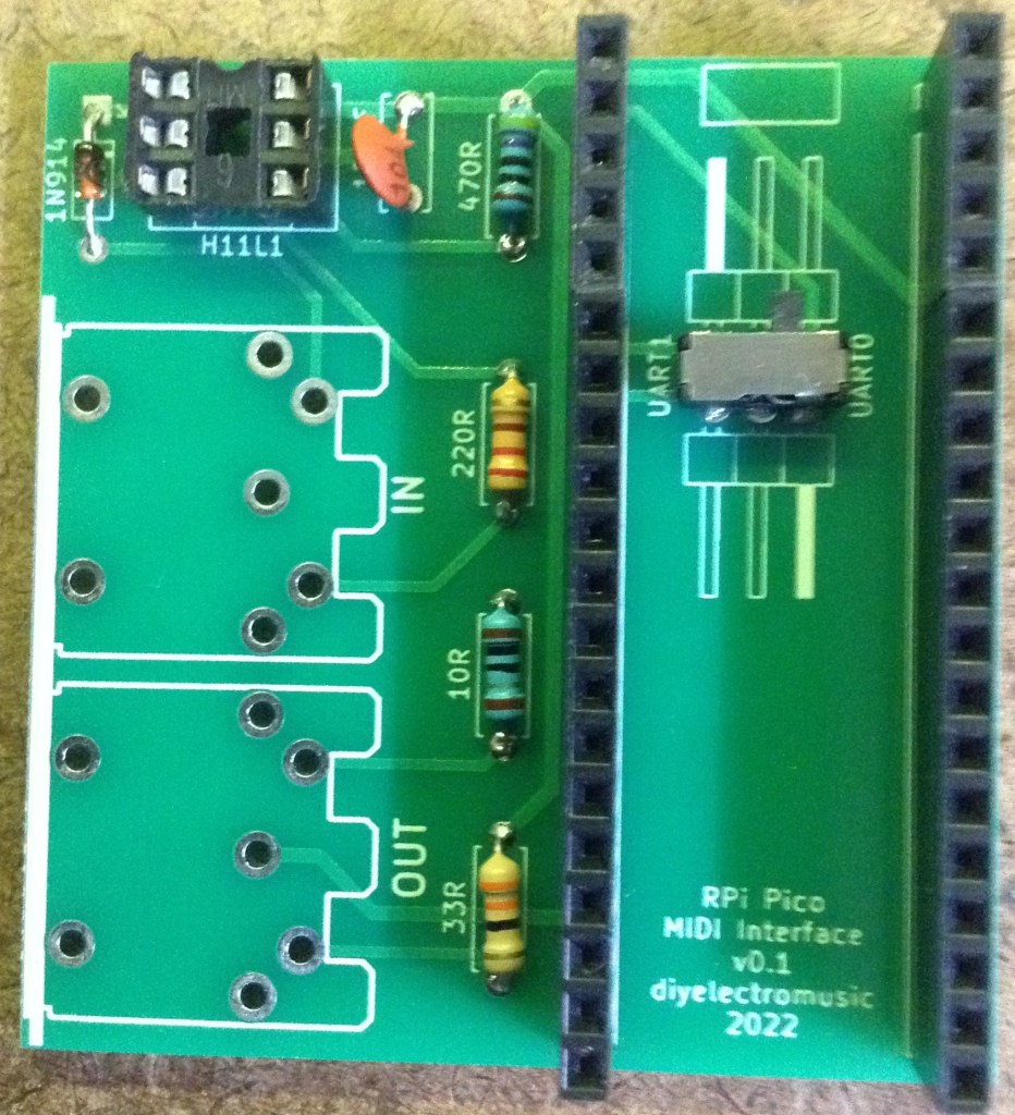
Here is the board after installing the passive components and the 6-pn socket.

There are various options for the UART select:


If not using pin header sockets for the Pico, then you must ensure adequate clearance between the Pico and the switch/headers/links underneath it…
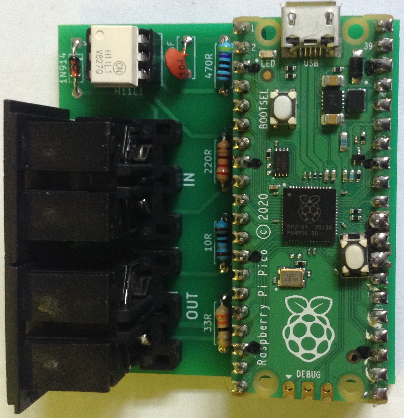
Here is the final board prior to inserting the H11L1 and the Pico.

Testing
I recommend performing the general tests described here: PCBs.
PCB Errata
As already mentioned, the capacitor is mislabeled and should be a 100nF ceramic capacitor (not 100uF as written on the PCB).
Otherwise, nothing major that I can see. There is an errant “K” on the silkscreen near the diode that I’d not spotted and I might find a better way of indicated the UART headers…
Potential Future Enhancements:
- It might have been nice to have included some mounting holes.
- The two structural solder pads for each MIDI socket could be turned into rectangular pads for more support when inserting/removing jacks (I’ve done this on later boards).
You can find the PCB design files on GitHub here: https://github.com/diyelectromusic/sdemp_pcbs/tree/main/PicoMIDIPack
Closing Thoughts
As I mentioned last time I once again went with the Seeed Fusion pcb service as I got on fine with them for my first try and I had some vouchers to spend back with them which meant these boards could be made for free. Just to be clear, I am not sponsored by or affiliated with anyone, but like anyone I’m very happy to use discounts!
Once again the boards were returned really quickly, were relatively cheap and seem perfectly fine as a result. I’d be very happy to use them again for future boards and in fact, as of writing have some more on the way back to me too.
Kevin

