I’ve been toying with the idea of some kind of IO board for my MiniDexed experiments for use with a Raspberry Pi. I initially wanted something fully self-contained – i.e. just pop it on a Raspberry Pi and you’re good to go. But then it was pointed out that having all the IO connections on one side is much more friendly from a “putting it all in a case” point of view.
- Update: There is now a newer version of this design for the SSD1306: MiniDexed Raspberry Pi IO Board V2 Design.
In the end, I used many of the same circuit elements and came up with two designs.

Update: Here are links to the build guides for these PCBs:
There is a version for the Raspberry Pi V1 here: MiniDexed Raspberry Pi V1 IO Board and my pseudo TX816 can be found here: MiniDexed TX816.
Warning! I strongly recommend using old or second hand equipment for your experiments. I am not responsible for any damage to expensive instruments!
These are the key tutorials for the main concepts used in this project:
- My first experiments in KiCad: Arduino Uno Dual Merge MIDI “Shield” – Part 2
- MiniDexed: “Bare Metal” Raspberry Pi MiniDexed DX7
If you are new to microcontrollers and single board computers, see the Getting Started pages.
Basic Requirements
I wanted a board to do the following:
- Include a screen or display.
- Have MIDI IN.
- Optionally include MIDI OUT and THRU.
- Have a rotary encoder for input.
- Incorporate a PCM5102 DAC for audio output.
- Optionally include a couple of buttons.
As I mention above, I was initially after something that would fit within a normal “HAT” type footprint for a Raspberry Pi, which is pretty constraining, but following on from the Clumsy MIDI board, should be possible with a small SSD1306 OLED display.
But I was also keen to try to build something that would allow all the IO to line up along the back, so I’ve also designed a larger board that overhangs the Pi and allows for a full three MIDI din sockets. This larger board can accommodate a HD44780 LCD display as used in the original MiniDexed setup.
I’m happy for the whole thing to receive power via the Pi and of course USB and ethernet connections are also available on one side.
MiniDexed RPi IO Board (SSD1306 Version)
Starting a new project in KiCad, there is already a “Raspberry Pi 40-pin Extension Board” template which provides the basic outline, PCB footprint for the GPIO, and cut-outs for the display and camera.
Here is the schematic I’m working to.

Points worthy of note:
- A H11L1 based MIDI IN circuit connected to RX0.
- A rotary encoder (not a KY-040 module) is used with 10pF capacitors for debouncing the connections.
- A PCM5102 in the “GY module” format (as used by Clumsy MIDI).
- Two optional button push-switches which are also broken out to headers, also with debouncing capacitors.
- I’ve included the header for the SSD1306 in SDA-SCL-VCC-GND format.
This is the GPIO map used:

If the rotary encoder seems to be “backwards” then swap RE_A and RE_B in the configuration. Note that at the time of writing, I2C SSD1306 displays are in development but hopefully will be available in MiniDexed by the time you read this.
Here is the board that has been sent off for manufacturing.

Design notes:
- I used the GY-PCM5102 symbol and footprint library from the Clumsy MIDI GitHub repository.
- The H11L1 is upside down as that made routing easier.
- I’ve included footprints for two push-buttons (the very common “through hole” type used in many maker projects) but also included two sets of header pins so these could be wired off to something else if required.
- I’m using a 32×128 OLED (again the same one used with Clumsy MIDI). As I say, MiniDexed doesn’t support this directly at the time of writing, but I’ve submitted a PR for support that is waiting to be accepted, so hopefully it will be fully supported soon.
- Unlike my previous boards, I used a filled zone to create a link to the GND net and provided a ground plane on the rear copper layer of the board.
- Both the SSD1306 and PCM5102 modules I’m using have a built-in regulator to take 5V down to 3V3. This is particularly critical for the SSD1306 as it includes pull-ups for the I2C connection to the 3V3 level (not 5V). But this is why they are hooked up to 5V yet I’m not using level-shifters to interface to the (3V3 logic) Pi.
Here is an early “space test” (without the buttons) with a paper printout to give you an idea of what I’m aiming for.

And an image of the Gerbers as sent off for manufacture:

MiniDexed RPi IO Board (HD44780 Version)
Again starting a new KiCad project from the Raspberry Pi 40-pin extension board template, this is the circuit I’m working with for this one.

Schematic Notes:
- This is using the same PCM5102, rotary encoder, and switches as above (although I’ve just realised I never swapped the schematic and pcb over to use the GY-PCM5102 module symbol and footprint – oh well, for this board it is a 6-way set of headers!).
- This uses the “data interface” version of the HD44780. I did think about using the I2C version, but thought this would be the simplest case to build if it could be made to work.
- There is MIDI IN, OUT and (optional) THRU.
- The MIDI circuit borrows heavily from Clumsy MIDI and includes a 74HCT14 hex inverter as an output buffer for OUT and THRU (although it is labelled as a 74HC14 on the schematic and pcb).
- THRU is optional, in which case the unused inputs to the 74HCT14 should go to GND instead (selected by solder jumpers).
- OUT can optionally be changed to a(nother) THRU rather than an OUT, in which case it can be switched via solder jumpers to be connected to RX0 rather than TX0.
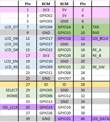
To simplify the routing of the PCB, the pinouts for the various components have changed. Here is the pinout being used (this is now quite different to the original MiniDexed pinout).
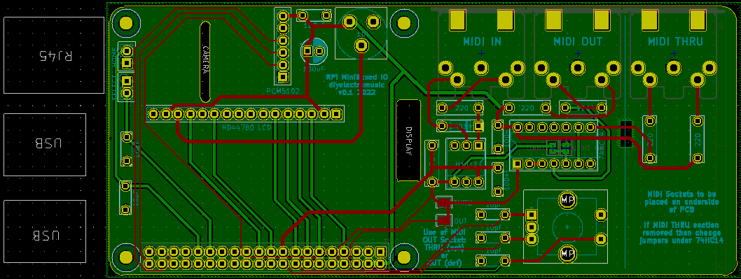
So this is the design for the pcb that has been sent off for manufacture:
Design notes:
- The PCB is designed to be used with a Raspberry Pi “upside down”. That is, with the connectors at the top, and GPIO at the bottom. This means the USB/RJ45 ports will be on the left hand side, as shown.
- The MIDI THRU section is optional. If only two MIDI sockets are required that part of the board can be cut off along the line indicated. If that is done then the solder jumpers beneath the 74HC14 must be changed as follows:
- Cut the “THRU” jumper (this disconnects the 74HC14 from RX0).
- Solder the “NO THRU” jumper (this connects the unused 74HC14 port to GND).
- The MIDI OUT port can be changed to a THRU too. If the original THRU is removed, this means you can just have MIDI IN and THRU instead of IN and OUT if you wish. If the original THRU is retained, then you can have a MIDI IN and two THRUs. To turn the OUT into a THRU change the two solder jumpers near the H11L1 as follows:
- Cut the “OUT” jumper (this disconnects the OUT circuit from TX0).
- Solder the “THRU” jumper (this connects the OUT circuit to RX0 to make it a THRU).
- Whilst on the subject of MIDI sockets, all three sockets are oriented to go underneath the board so they will go alongside the RPi.
- The optional buttons are not provided on the PCB, but via two sets of headers on the left hand side of the board.
- As mentioned above, annoyingly I forgot to change the PCM5102 footprint to that of a GY-PCM5102 module, so there are no holes for the additional 9-way header. These are not used electrically, but they would have provided some additional physical support. Instead I might solder some header pins and use the plastic pin spacer as a support under the board (but I’ll look into that when I get the boards back).
- I’ve included a simple “preset” pot to control the contrast for the LCD.
- Once again I used a filled zone to create a link to the GND net and provide a ground plane on the rear copper layer of the board. Note that I left a cut-out under the traces to the THRU part of the circuit, to reduce the chance of a short if the board is cut off at this point.
- Most LCD1602/HD44780 modules are 5V parts, with 5V required to ensure the LCD actually illuminates successfully. However, as described here, it is usually ok for a 3V3 output to drive a 5V input, so as long as the LCD isn’t attempting to drive the IO pins for the Pi, the Pi should be fine talking 3V3 to the LCD. So that is the approach I’m taking. It does mean that this won’t accept a 3V3 LCD module. But in all this, remember my level of electronics experience, and make up your own mind…

Manufacturing
Both boards should be built using the standard, cheapest manufacturing options. Both are fine with a 6/6 mil constraint on track width and separation.
The second board is somewhat larger than the common “cheap” tier. For me, all my other boards were $4.60 plus postage for 10 boards, but the larger one has jumped up to around $27 plus postage.
On the back of my first blog post, having used Seeed Fusion to produce my first boards, they sent me some money off vouchers, so I’ve used them once again here. That was particularly welcome given the increased cost of the larger board!
I still don’t really have a space to store these designs. But I’ll update this post when I do!
Closing Thoughts
Although either of these designs could potentially be used in a case to make a nice, small, self-contained unit, I can’t guarantee that the spacing of connectors and components will really allow it. I’m also not sure what will be required in terms of cooling for the Pi, so I’ll have to see how I get on. It may be that I’ll need more spacing between the Pi and the IO board.
I’m still learning with KiCad, so am fully expecting continued mistakes or odd design choices, but I think both of these will be interesting to try.
Update: mistakes already spotted since sending them off:
- The afore-mentioned GY-PCM5102 footprint error.
- Labelling on the board states 74HC14 and it really has to be a 74HCT14.
So that is the walk-through of the design of these boards. Of course I won’t really know if they are successful until I get the boards back from manufacturing!
Kevin

Wow! This is truly amazing stuff! Could we also have a two piece PCB version? What I had in mind was a separate backpanel PCB which would contain TRS audio, TRS-A MIDI x 3 (in, out & thru), ”external” USB-A port cable which is connected to Pi4 USB-A port and ”external” USB-C port cable which is connected to Pi4 USB-C power port? You would then connect Pi4 to the backpanel PCB via flat GPIO cable. The second PCB would contain the screen and the encoder, and that PCB would be connected to the backplane PCB via flat cable or Dupont cables. I would also prefer, if the encoder was vertically centered with the screen 😉 With just the pins on the backplane PCB and Dupont cables you could of course place your screen and encoder wherever you want, so maybe that would be better choice.
This setup could be used with slimmer cases or even built inside MIDI keyboards. Users could then design their own backplane covers to the case or keyboard, etc. Here’s a link for kind of a concept I had in mind (scroll to the bottom of the screen): https://www.deepsonic.ch/deep/htm/korg_opsix.php
Thank you very much for your contribution to the community and Happy Holidays!
LikeLike
Thank you for your suggestions, but I’ve no plans to revisit this particular type of board at present, but if I do, then something that allows for more flexible mounting, possibly Zynthian style, could definitely be one way to go.
Yes, I was reading about the opsix recently, I think in the MagPi Magazine. Interesting that it uses a Pi CM4…
Kevin
LikeLike
Hello Kevin,
My name is Douglas, I’m Brazilian, and I already messaged you last week about your project.
I assembled your project this weekend inside a Yamaha DX9 keyboard, and it turned out perfectly. Now I have a DX9 with DX7 sounds, the DX9 controls the minidexed via MIDI, and even the keyboard buttons respond. I appreciate your development, as it was essential for the completion of my project. I was already thinking about including a computer in my DX9 to emulate the DX7, but when I saw your project with the Raspberry Pi, I understood that this was the path I needed. I used a Raspberry Pi P3B. Allow me to make a correction to your documentation; I really didn’t find this information anywhere, so I’ll assume the error exists. If it’s described somewhere, I apologize. I assembled my board based on your IO-Board-HD44780 design, revised on 09/15/2012. This entire circuit is correct and functional except for the pinout of connector J2, which is the LCD connector. The pinout in the drawing is incorrect; the digital data 04 to 07, LCD_EN, VO, among others, are incorrect. The output pins for the Raspberry Pi in your project are correct, but the pinout for the LCD connector in the drawing is wrong. I identified this during the circuit assembly. By the way, I deactivated 7 instances of DX7 in the .ini file so I could operate with only 1, since my use will be for studio applications and mainly with E.Pianos, so I think it’s better this way. The result was incredible.
Best regards and thank you again for sharing the project.
LikeLiked by 1 person
Curious. I’ve definitely built this and it is working for me 🙂 Maybe you have a different style of LCD? What did you find was wrong and in which diagram?
Glad you got everything going though.
Kevin
LikeLike