Following on from part 1, I’ve added BT style sockets and upgraded the ringer to ring two phones. Polytelephony if you will. In part 3, I switch to an Arduino Nano and put all the circuitry into a box.
Warning! I strongly recommend using old or second hand equipment for your experiments. I am not responsible for any damage to expensive instruments!
NEVER CONNECT ANYTHING DESCRIBED HERE TO A REAL PHONE SYSTEM AND BE VERY, VERY CAUTIOUS OF WORKING WITH THE VOLTAGES DESCRIBED HERE.
These are the key Arduino tutorials for the main concepts used in this project:
- Arduino MIDI Library
- Arduino Timer One Library
- Interface L298N DC Motor Driver Module with Arduino
- 250W Boost Converter Module DC 8.5V-48V to 10-50V
If you are new to Arduino, see the Getting Started pages.
Parts list
- Arduino Uno
- L298N “H Bridge” DC Motor Driver
- 250W Boost Converter Module DC 8.5-48V to 10-50V
- Two GPO 746 original vintage telephone
- Sacrificial telephony devices with a BT style socket
- MIDI Interface
- MIDI controller
- 12V power supply
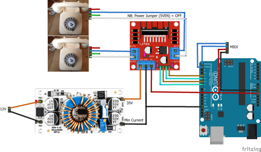
The Circuit
All the details required to get the basic circuit up and running for a single phone are described in part 1, so I won’t go over that again here. The H-Bridge has support for two motors, so it is relatively straight forward to use that to drive a second phone. I just need to connect two more Arduino digital pins to the IN3 and IN4 inputs and the second phone to the OUT3 and OUT4 connections.
Scavenging BT Phone Sockets
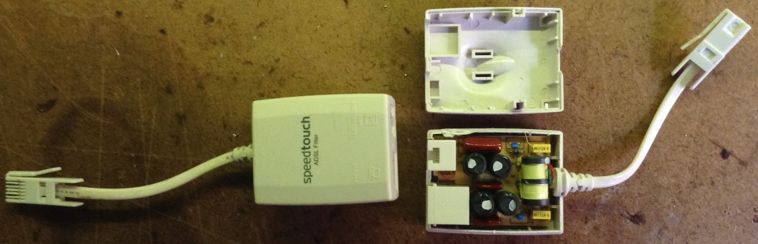
In order to allow me to simply plug in my phones, I wanted a couple more BT phone sockets. I found an old BT “master socket” and another ADSL filter, so once again I stripped them of the components and then soldered on the appropriate connectors. Here are a few photos. Remember I’m after a connection between the “blue” and “white” pins for the BT socket.
First the BT socket…


The the other ADSL filter. There were a lot more components on this one compared to the last one I took apart!


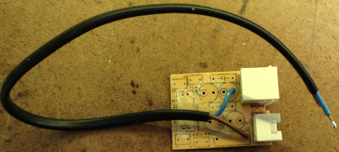
Each “ringer” circuit now has a proper socket on the end.

The Code
This is using the same code as in part 1, but with all the sections associated with enabling and driving the ringer circuits duplicated to allow for a second ringer.
I’ve taken out the multi-frequency aspect though as it didn’t seem to be working particularly well and I can’t simply have the timer interrupt routine running at two different frequencies. So I’ve just configured it for the UK 25Hz frequency.
I have allowed each ringer to be assigned to multiple notes however.
Closing Thoughts
Most of the limitations from part 1 remain, but at least now I have proper sockets to plug the phones into. I do need to do something about a case for the bulk of the circuitry though…
And all this only works with my vintage rotary telephones with real bells inside. I have a touch phone from the 80s that can do either pulse or DTMF tone dialing, but this won’t ring that unfortunately. Yet.
Kevin
