One thing I love about those vintage rotary telephones is the characteristic ring. But making them do that outside of being plugged into the PSTN isn’t easy. But I wanted to see if I could make it work over MIDI, so this is my approach.
- In part 2 I add some BT style sockets and extend it to a second phone.
- In part 3 I put all the circuitry into a box.
Warning! I strongly recommend using old or second hand equipment for your experiments. I am not responsible for any damage to expensive instruments!
NEVER CONNECT ANYTHING DESCRIBED HERE TO A REAL PHONE SYSTEM AND BE VERY, VERY CAUTIOUS OF WORKING WITH THE VOLTAGES DESCRIBED HERE.
These are the key Arduino tutorials for the main concepts used in this project:
- Arduino MIDI Library
- Arduino Timer One Library
- Interface L298N DC Motor Driver Module with Arduino
- 250W Boost Converter Module DC 8.5V-48V to 10-50V
If you are new to Arduino, see the Getting Started pages.
Parts list
- Arduino Uno
- L298N “H Bridge” DC Motor Driver
- 250W Boost Converter Module DC 8.5-48V to 10-50V
- GPO 746 original vintage telephone
- MIDI Interface
- MIDI controller
- 12V power supply
The Circuit
These old vintage telephones are designed to work on a DC biased -48V to -50V supply over the telephone line with a 75-80V AC ring signal that is sent down the wire to make them ring. Understanding how it all works is largely beyond me, but here are some references if you want to find out more yourself:
- How Telephones Work (British Telephones.com)
- Telephone Ringing Circuits (epanorama.net – I get “trojan” warnings for this link, so I used the Google Cache version)
- Telephone Line Audio Interface Circuits (epanorama.net – again, I used the cached version)
- Making (Old) Telephone(s) Ring (Arduino Forum discussion)
- Arduino-Controlled Rotary Telephone (DIY Escape Room Prop Tutorial) (Playful Technology on YouTube)
Just to repeat the caution from the start of this post. Technically I believe anything below 50V is considered “extra low voltage” and anything in the (AC) range 50-1000 is low voltage (see here), but really the issue is how much current is available with it, which is why a 12V car battery can be quite dangerous to be around. I don’t know what the risks of anyone trying to follow this project will be, so I can only recommend that you don’t. This is a step up from messing around with MIDI and “common” Arduino IO voltages, so if you are in any way unsure, really, I suggest you don’t. I will repeat my usual mantra here – “I am not an electronics person” – so don’t assume I know what I’m talking about. I know enough to be cautious for myself, I strongly urge you to do the same.
A few of these resources suggest you can use a H-Bridge motor control circuit to switch the voltage to the phone on and off at the required frequency, when driven from an Arduino, which sounds very promising.
The question then becomes how should that driving voltage be generated? There are different standards for ringing signals around the world, but in the UK I need a 25Hz square wave at something like 60-80V.
Some ideas included:
- First of all seeing if something is available commercially. It turns out that yes, there are companies out there that will sell you a “ringing box” often for use as a “live” prop in stage productions.
- I also wondered about a second hand exchange, especially as networks around the world slowly turn off their old analog connections.
- Use a 50V+ power supply.
- I saw reference of “using a transformer backwards” so thought this might be worth a look.
- I’ve seen a number of “boost” converters to generate higher voltages from a lower voltage input, so again I thought that worth a look.
With regards to the first three, as always I was particularly keen to see what I could do on a small budget, and also as always was interested in trying to find out how to do it myself if at all possible. So after finding there was no real solution in any of these for “silly money”, I started to think about the last two.
On Transformers…
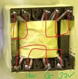
I had an old printer power supply that I thought might have a useful transformer in it.
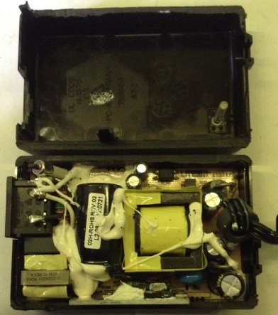
But after a bit of experimenting around and some discussion on Twitter, you need a fairly simply transformer setup for anything like this to work in the way I need. Most modern PSUs are switched-mode power supplies and so will use a transformer designed for that use. They rely (as I understand it) on high frequencies and feedback to maintain the transformer functionality in a small physical space with high efficiency.
The upshot is that a SMPS “flyback” transformer is no good for what I’d like to use it for.
I have a simple, cheap one on order to give that a go, but whilst it seems that you can use a step-down transformer as a step-up one, there are a number of design considerations to think about. The main one being any asymmetry in design of the two sides, with regards to voltage, current and power specification – that has to be thought about quite carefully.
In short, I don’t really know what I’m doing here, so have shelved this one for now.
On boost converters…
I’ve seen these modules fairly regularly in my general electronics browsing but have never really taken a detailed look at how they work. On the face of it they sound impossible – get more out than you put in! Of course they don’t actually work like that and the physical reality of the universe does remain intact with their use, but I must confess I’m still not totally sure I understand the theory of their design.
So I wasn’t sure if I could use one for this application or not, but thought I’d have a go regardless. I ended up with one like the following:
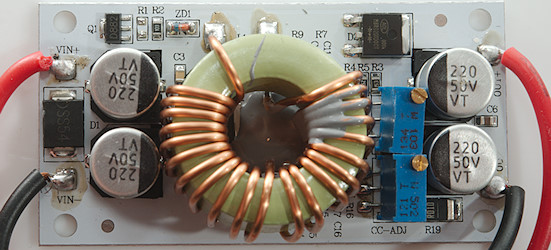
Called a “250W DC-DC Step Up Adjustable Power Supply Module, Boost Converter” (or words to that effect) it has the following spec on paper (taken from a listing of one of the modules for sale):
- Module Properties: Non-Isolated Boost Module
- Input voltage: DC 8.5V-48V
- Input current: 10A (MAX)
- Static operating current: 10mA
- Output voltage: 10-50V continuously adjustable
- Output current: 10A MAX
- Constant current range: 0.2-8A
- Potentiometer: CC is constant current regulation; CV is constant voltage regulation.
If you plan on using it towards the higher ends of the specs then it appears advisable to provide additional heat dissipation. There are two multi-turn pots on the board, one to adjust the output voltage and one to (as I understand it) limit the output current.
The basic idea is that you set it up and then measure the output voltage whilst turning the “voltage” pot (top) anti-clockwise to increase the voltage to your desired level. Then have the “current” pot (bottom) fully turned clockwise to start with a minimal current and adjust as required.
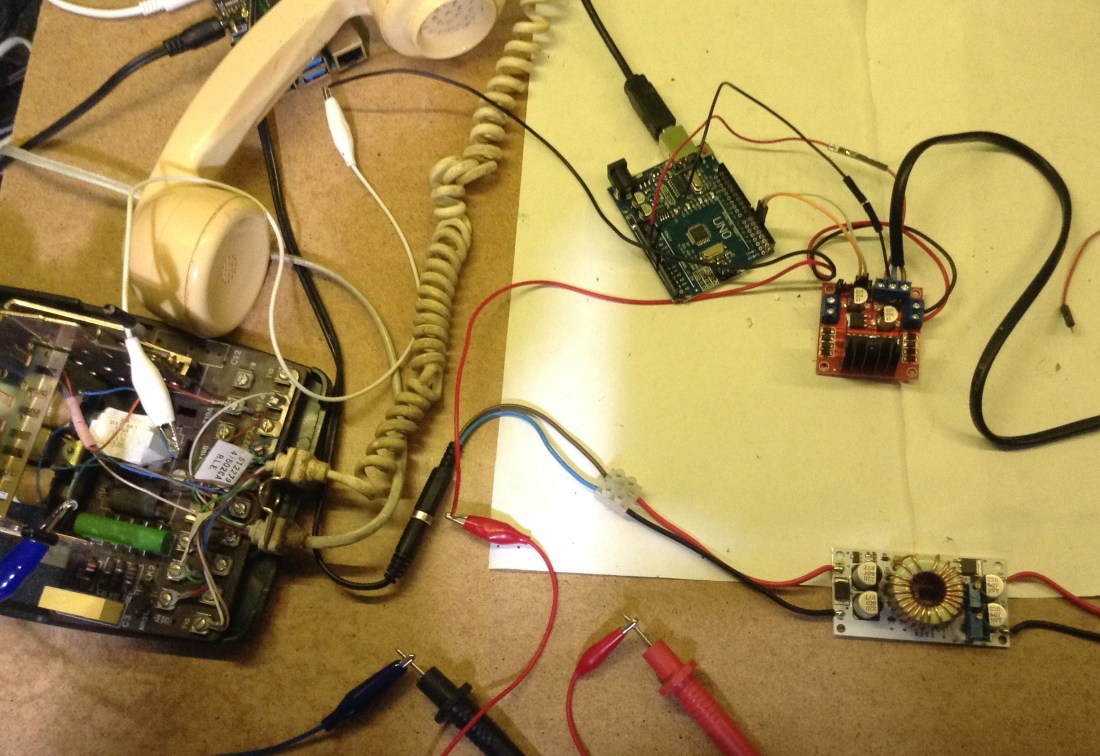
The final circuit
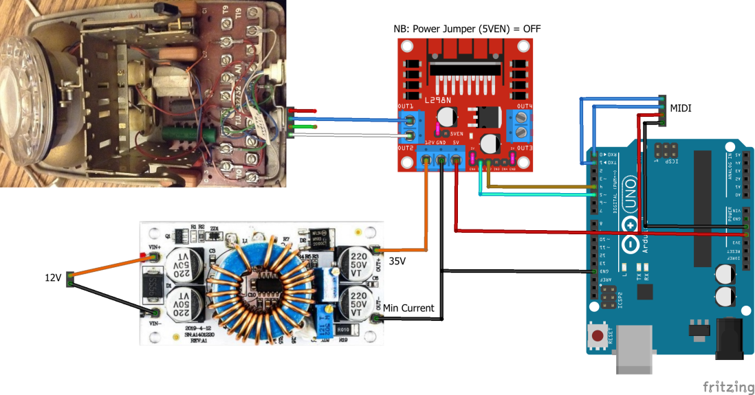
This is what I’ve ended up with:
- I supply 12V to my boost converter module and tune it to 35V on the minimum current setting.
- I’m using a L298N DC Motor Controller like the one in the diagram. This supports a maximum driving voltage of 35V hence using that as the limit for the boost converter. Notes on the use of this module:
- For detailed instructions, see the “Last Minute Engineers” tutorial here: https://lastminuteengineers.com/l298n-dc-stepper-driver-arduino-tutorial/
- As I’m using a drive voltage that is more than 12V I’ve disabled the onboard regular that generates the 5V signal for the logic side of things by removing the 5VEN jumper. This means I need 5V from the Arduino.
- I’m only using one of the motor connections, so I’m using Motor OUT1 and OUT2 and control inputs IN1 and IN2.
- I’m not using PWM control, so a jumper is required for ENA.
- IN1 and IN2 are connected to Arduino D4 and D5.
- The telephone circuit in these old phones has a “bell wire” which is used when the phone is “on hook” to drive the ringer circuit. This means the output from the H-Bridge has to be connected to the blue and white wires, assuming the standard BT wiring.
- In order to drive the whole thing from a MIDI keyboard I need a MIDI module hooking up to the Arduino’s RX/TX pins in the usual way.
As I wasn’t quite sure what I was doing, I took several precautions on the way:
- I tinned all wires for the screw terminals, and used 5A mains blue/brown wiring (as I had some spare from some old power leads), and normal 5A mains screw connectors.
- I checked the operation of the boost converter before wiring it up to the H Bridge.
- I checked the operation of the Arduino before wiring it up to the H Bridge, including checking the signal frequency and levels on my oscilloscope.
- I did the usual “approximate ohm’s law” check for 35V and 2x2kΩ coils to think about the theoretical (DC) current use. 35/4000 = 8.25mA.
- I checked the operation of the boost converter and H-Bridge from the Arduino before wiring it up to the phone by checking the output of the H-Bridge using my oscilloscope.
- I tested everything using just the ringer module/coils in the phone – i.e. I disconnected them from the rest of the phone circuitry.
- When I connected it all up, I used my multimeter to measure the current passing through the coils when ringing this way (I think it was <0.5mA peak and typically much less, although I’m not really sure I have the tools to accurately measure AC current).
- I’ve not left it running unattended and once experimentation is over will ensure it all gets built into a case.
Amazingly, this seems to work and nothing started smoking, so I’m calling it a “win”. And this does appear to work from the “outside” of the phone, so I think I can make an unmodified phone ring using this setup.
A note of caution (only one?). I have a “converted” GPO 746 phone that has a pair of 2kΩ coils in series in the ringer circuit. An “unconverted” phone typically has two 500Ω coils, so I make no claim to knowing what I’d have to do with one of those.
Once thing that might work in our favour though, is the video I’ve linked to above also seems to have a dual 500Ω ringer unit and the author appears to show it working straight off a 12V power supply with no boosting of voltage required.
I did try that first and whilst I could hear “ticking” – i.e. I could hear the phone trying – I didn’t get it ringing. I wonder if the power at 12V through 4kΩ just wasn’t enough to make them ring – the current will be 4x lower in my case compared to dual 500Ω coils, hence I do seem to need a higher voltage.
I did have a moment of fun irony in all this though. That old printer PSU I took apart to try the transformer… that had 32V and 16V outputs. It is quite possible that the 32V output might have been enough if I’d used it directly to drive the H Bridge. I almost soldered the transformer back in place to try. Almost.
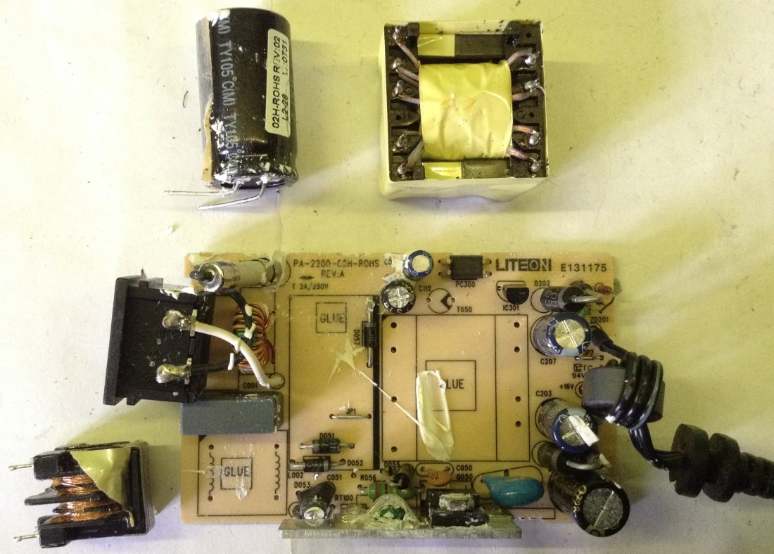
But I’m not one to mess around with a PSU like that, especially after I’ve sawn the casing open, so instead I desoldered a few other useful looking components and threw the rest away to remove temptation.
But hindsight is a wonderful thing 🙂
The Code
The basic code to drive the H-Bridge to generate my 25Hz square wave is quite straight forward really. I’ve used the TimerOne library to configured a timed interrupt running at twice the required frequency. This is used to toggle the IO pins driving the H-Bridge.
The basic idea for controlling this over MIDI is as follows:
setup():
Configure IO pins
Initialise MIDI handling
Disable the output
Configure the timer interrupt for 50Hz operation (2x25Hz)

loop():
IF note pressed THEN
  Enable the output
IF note released THEN
  Disable the output

Timer Interrupt Routine:
IF output enabled THEN
  toggle output flag
  Set IN1 to output flag
  Set IN2 to NOT output flag
IF output disabled THEN
  Set both IN1 and IN2 to LOW
The only slight quirk is that TimerOne requires the period for the tick, not the frequency. Also as I want a square wave generating, that means “go HIGH” for one tick then “go LOW” for one tick, which is why the “tick” needs to be running at twice the frequency of the required waveform.
The period can be calculating using:
unsigned long tickperiod = 1000000UL/(((unsigned long)freq)*2);
Timer1.setPeriod(tickperiod);
Note the enforced use of 32-bit arithmetic to prevent overflows in the calculation.
In principle I should be able to make it ring with different frequencies. Note this is not frequency as in pitch – that is governed by the bells themselves – but frequency as in “how often they are hit”.
In the code I’ve allocated the notes C4, D4, E4 to 20Hz, 25Hz, 30Hz. I’ve checked with a scope and they do produce the different frequencies, but I can’t hear any actual audio difference myself. I guess if this is required then more significantly different frequencies will have to be used!
Closing Thoughts
I was quite surprised that this was possible. I thought I would have to get involved in much more of the higher voltage, analog electronics details of phone systems.
Of course there are significant limitations:
- Hopefully it goes without saying that this can NEVER go near any kind of real phone connection.
- I’m not really doing this in a way that is compatible with my previous vintage phone setup.
- I’m not really doing anything here to “protect” against those voltages. It really needs some casing!
Ideally I’d find a way to both allow the ringing and still handle the pulse dialing, but I’m not sure if that is even possible at present.
At the very least I’d like to try to build this into a case with a proper BT phone connection and just the 12V power connection. That is probably possible and I might ponder that next.
Kevin
